Buy in one click, pay by GCash, Maya, QR Ph or PayPal, and your download appears as soon as the payment clears.
All products are non-refundable. Please check the details and price before you pay. Licensed to the buyer only (one engineer or office). Sharing, uploading or reselling a product, or forwarding its download link, without the written permission of RHCES is prohibited. By buying you agree to our Terms of Service.
No spreadsheets match that search.
Precast
Corbel Designer (NSCP 2015)
by RHCES
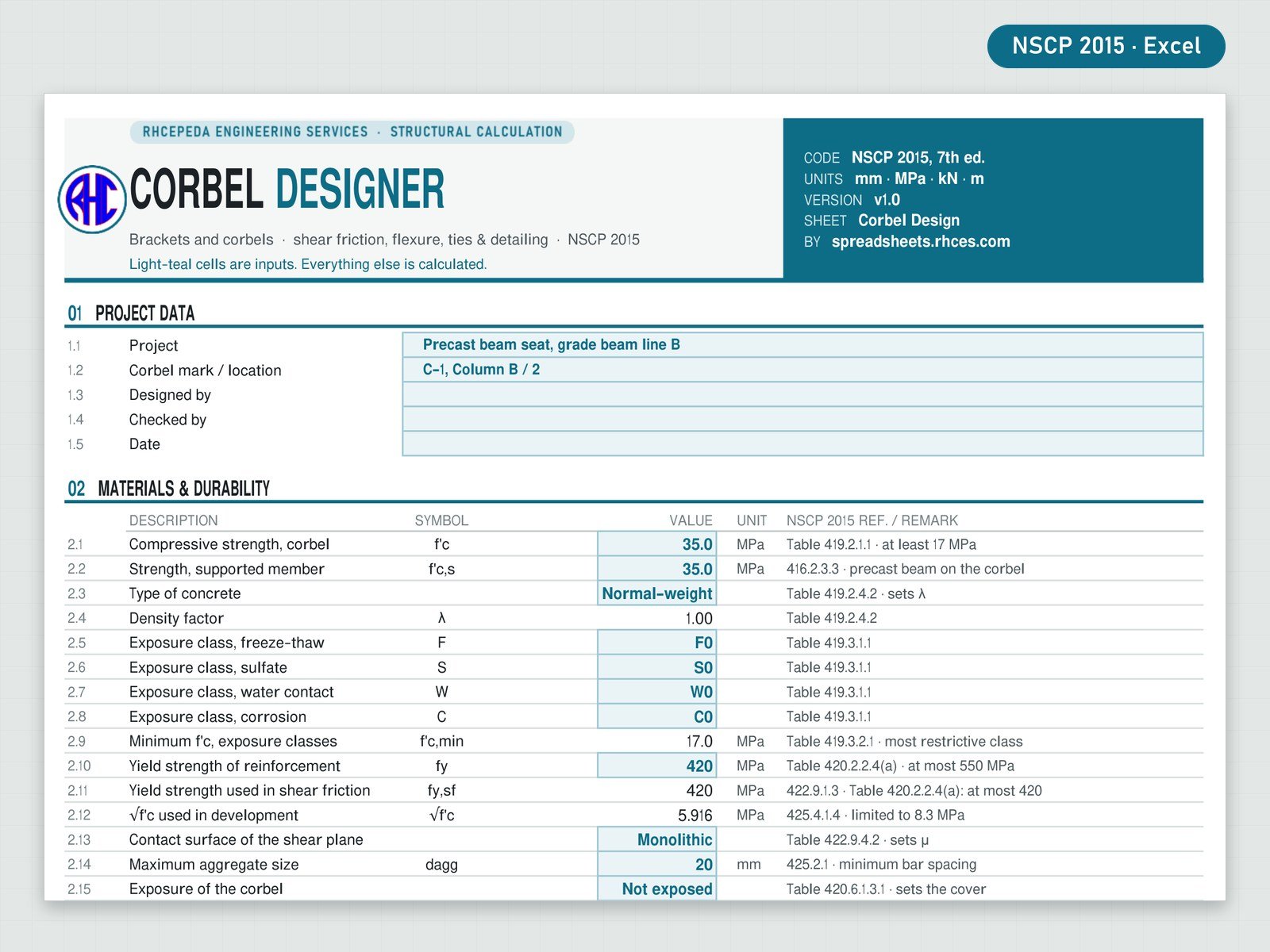
Design a reinforced-concrete column corbel or bracket (sloped or straight soffit) by the traditional method of NSCP 2015 Section 416.5: the applicability limits (av/d, Nuc not above Vu, outside depth, bearing area against the tie anchorage), the limit on Vn, shear friction, flexure with direct tension, the primary tension steel Asc and the closed ties Ah, bearing under the plate, cover, bar spacing and development at the column face, plate set-back and bearing of the lesser surface.
Enter the corbel geometry, the bearing plate, the materials, Vu and Nuc (or let the sheet take the minimum tension) and the bars; it reports every check with demand, capacity, ratio and PASS / FAIL, a live elevation of the corbel with the bars, and one overall result. Strut-and-tie design is out of scope (the Read Me says where it applies).
Every result is a visible Excel formula with NSCP 2015 clause references. Includes the Excel workbook and a worked A4 sample calculation. One licence per engineer or office.
Design a reinforced-concrete column corbel or bracket (sloped or straight soffit) by the traditional method of ACI 318-19 Section 16.5 (SI units): the applicability limits (av/d, Nuc not above Vu, outside depth, bearing area against the tie anchorage), the limit on Vn, shear friction, flexure with direct tension, the primary tension steel Asc and the closed ties Ah, bearing under the plate, cover, bar spacing and development at the column face, plate set-back and bearing of the lesser surface.
Enter the corbel geometry, the bearing plate, the materials, Vu and Nuc (or let the sheet take the minimum tension) and the bars; it reports every check with demand, capacity, ratio and PASS / FAIL, a live elevation of the corbel with the bars, and one overall result. Strut-and-tie design is out of scope (the Read Me says where it applies).
Every result is a visible Excel formula with ACI 318-19 section references. Includes the Excel workbook and a worked A4 sample calculation. One licence per engineer or office. Looking for the Philippine code? See the NSCP 2015 edition.
Excel · A4 calc sheet + live corbel elevation · SI units
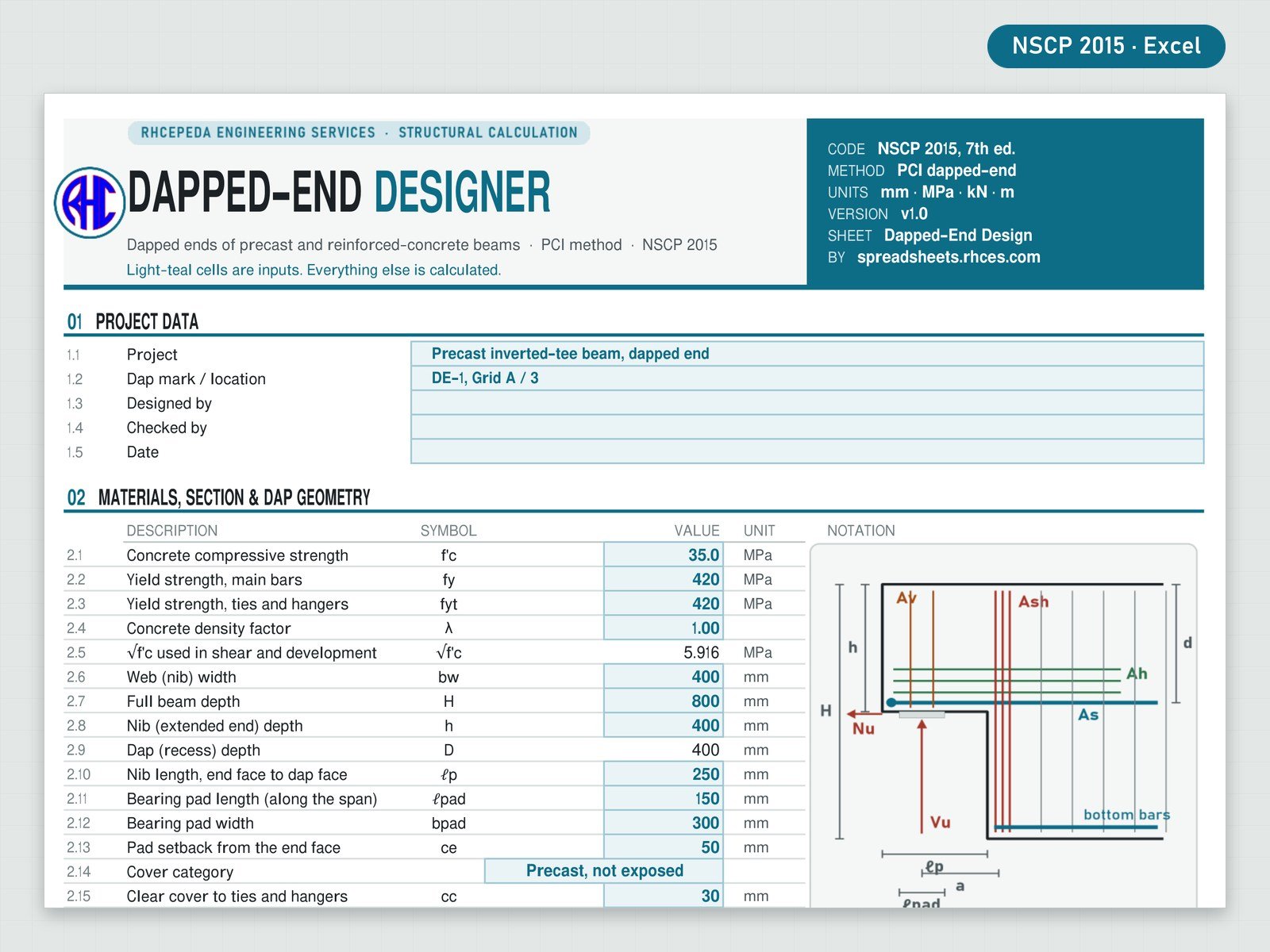
Design the dapped end of a precast or reinforced-concrete beam by the PCI Design Handbook method (Mattock & Chan 1979; PCI Design Handbook 7th / 8th ed.; Klein, Botros, Andrews & Holloway, PCI Journal 2017) in SI units, with every code part (phi factors, shear friction, bearing, development length, cover, bar spacing, minimum steel, shear) taken from the printed NSCP 2015.
The five PCI failure modes are designed and checked: flexure with axial tension in the extended end (nib); direct shear at the dap face by shear friction; diagonal tension at the re-entrant corner (hanger steel Ash); diagonal tension in the extended end (Av and Ah); diagonal tension in the undapped end with the anchorage of As and of the main bottom bars. Plus bearing, the minimum Nu, geometry limits, spacing and cover. A live elevation of the dapped end shows the nib, the re-entrant corner, the bearing and every bar group. Strut-and-tie is out of scope.
Every result is a visible Excel formula with NSCP 2015 clause references. Includes the Excel workbook and a worked A4 sample calculation. One licence per engineer or office.
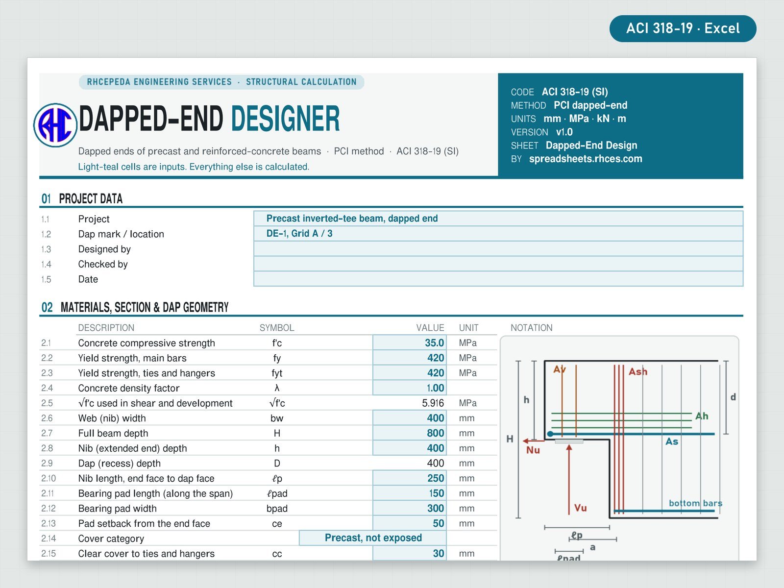
Design the dapped end of a precast or reinforced-concrete beam by the PCI Design Handbook method (Mattock & Chan 1979; PCI Design Handbook 7th / 8th ed.; Klein, Botros, Andrews & Holloway, PCI Journal 2017) in SI units, with every code part (phi factors, shear friction, bearing, development length, cover, bar spacing, minimum steel, shear) taken from ACI 318-19 (SI units).
The five PCI failure modes are designed and checked: flexure with axial tension in the extended end (nib); direct shear at the dap face by shear friction; diagonal tension at the re-entrant corner (hanger steel Ash); diagonal tension in the extended end (Av and Ah); diagonal tension in the undapped end with the anchorage of As and of the main bottom bars. Plus bearing, the minimum Nu, geometry limits, spacing and cover. A live elevation of the dapped end shows the nib, the re-entrant corner, the bearing and every bar group. Strut-and-tie is out of scope.
Every result is a visible Excel formula with ACI 318-19 section references. Includes the Excel workbook and a worked A4 sample calculation. One licence per engineer or office. Looking for the Philippine code? See the NSCP 2015 edition.
Excel · A4 calc sheet + live dapped-end elevation · SI units
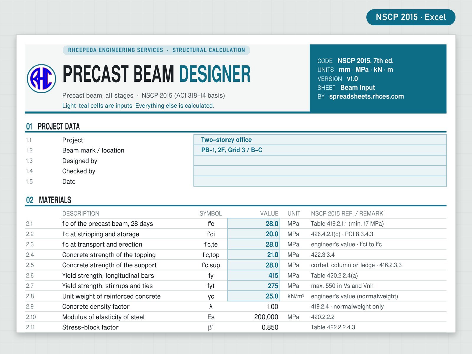
Design one reinforced (non-prestressed) precast concrete beam through its whole life by NSCP 2015 (7th edition): a rectangular, L-beam (one ledge) or inverted-T (two ledges) section, an optional cast-in-place topping, a simple span or continuity at one or both ends. The workbook follows the beam from the form to the finished floor in four handling stages, on its bearings, as a composite beam and at its supports, and names the governing check.
Checks: handling in four stages (stripping from the form, storage, transport and the erection lift) with the PCI equivalent static multipliers, the lift points, the sling angle, the crack-free limit fr/1.5 (a face over it is checked as a cracked section) and the insert load against your safe working load; erection of the precast beam alone, simply supported on its bearings under its own weight, the topping and the construction load, in flexure, shear and bar spacing; the final composite beam in flexure and shear, and the horizontal shear at the interface (416.4, with the interface ties); continuity, with the negative moment over the support by Table 406.5.2 from the loads placed after the topping hardens, the continuity bars in the topping, their spacing and development; the bearing: bearing length, pad set-back and bearing strength, the elastomeric pad (stress, thickness, rotation), the beam-end bearing steel (shear friction and the restraint force), and the grouted dowel in its grout tube (shear friction, embedment in the tube, development in the support, space in the tube, concrete round the tube, cover to the support face, grout strength, ties); cover, bar spacing, crack control and the deflections. All 53 checks are listed in the Design Check Summary with demand, capacity, ratio and status under one overall result: PRECAST BEAM ADEQUATE, ADEQUATE · SEE CHECKS, REVISE or CHECK INPUTS.
Four live drawings redraw from your inputs: the section with the ledges, the topping, the stirrups and the bars at true scale; the handling moment diagram of the governing stage against the crack-free limits; the factored moments of the erection and final stages against the design strengths; and the longitudinal section of the beam with its bars, stirrups, supports, pads, dowels and tubes. The sheet lists the factored reaction Vu, the horizontal restraint Nuc and the pad size to type into the RHCES Corbel Designer (column corbel) or the RHCES Dapped-End Designer (dapped end), both on this store.
Not covered: prestressed and post-tensioned beams (see the RHCES Prestressed and Post-Tensioned Beam Designers), the capacity of lifting inserts and the concrete breakout round them (the insert supplier), rigging and roll stability, ledge hangers and punching of the ledge, pad slip, proprietary grouted splice sleeves, torsion, seismic precast frames, lightweight concrete, fire rating. The pad, the design movement at the beam end and the tube and grout data are yours to supply; the Read Me lists them.
References: NSCP 2015, 7th edition; PCI Design Handbook, 7th edition; the strength, shear and bar-spacing checks are those of the RHCES RC Beam Section Designer v1.1 for the same code, with the printed page and the PDF page of each reference shown in the workbook.
The workbook was compared with an independent calculation of the sample, of the edge cases of every rule and of 300 random designs; its section checks agree with the RC Beam Section Designer v1.1 for the same inputs, and the pad, beam-end and dowel checks were also recomputed by hand.
Every result is a visible Excel formula. Includes the Excel workbook and a worked A4 sample calculation (16 pages: Beam PB-1, rectangular 350 x 550 mm, 7.50 m between bearing centres, f'c 28 MPa (f'ci 20 MPa at stripping), 4Ø20 bottom bars and 2Ø16 top bars, a 100 mm topping with 5Ø16 continuity bars at one end, a 250 mm bearing with a 15 mm pad, and one Ø16 dowel in a Ø50 tube at each end; result PRECAST BEAM ADEQUATE, governed by the clear bar spacing, ratio 0.88). The sample is illustrative. One licence per engineer or office.
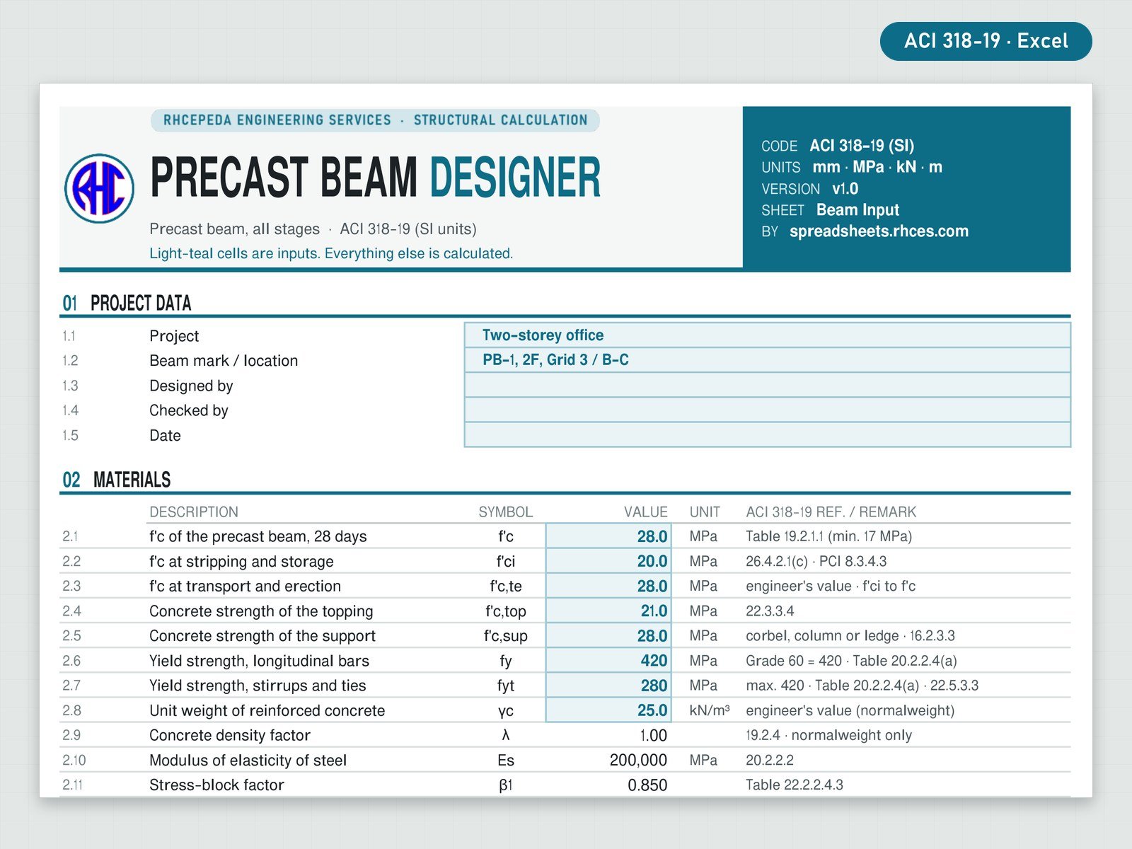
Design one reinforced (non-prestressed) precast concrete beam through its whole life by ACI 318-19 (SI): a rectangular, L-beam (one ledge) or inverted-T (two ledges) section, an optional cast-in-place topping, a simple span or continuity at one or both ends. The workbook follows the beam from the form to the finished floor in four handling stages, on its bearings, as a composite beam and at its supports, and names the governing check.
Checks: handling in four stages (stripping from the form, storage, transport and the erection lift) with the PCI equivalent static multipliers, the lift points, the sling angle, the crack-free limit fr/1.5 (a face over it is checked as a cracked section) and the insert load against your safe working load; erection of the precast beam alone, simply supported on its bearings under its own weight, the topping and the construction load, in flexure, shear and bar spacing; the final composite beam in flexure and shear, and the horizontal shear at the interface (16.4, with the interface ties); continuity, with the negative moment over the support by Table 6.5.2 from the loads placed after the topping hardens, the continuity bars in the topping, their spacing and development; the bearing: bearing length, pad set-back and bearing strength, the elastomeric pad (stress, thickness, rotation), the beam-end bearing steel (shear friction and the restraint force), and the grouted dowel in its grout tube (shear friction, embedment in the tube, development in the support, space in the tube, concrete round the tube, cover to the support face, grout strength, ties); cover, bar spacing, crack control and the deflections. All 53 checks are listed in the Design Check Summary with demand, capacity, ratio and status under one overall result: PRECAST BEAM ADEQUATE, ADEQUATE · SEE CHECKS, REVISE or CHECK INPUTS.
Four live drawings redraw from your inputs: the section with the ledges, the topping, the stirrups and the bars at true scale; the handling moment diagram of the governing stage against the crack-free limits; the factored moments of the erection and final stages against the design strengths; and the longitudinal section of the beam with its bars, stirrups, supports, pads, dowels and tubes. The sheet lists the factored reaction Vu, the horizontal restraint Nuc and the pad size to type into the RHCES Corbel Designer (column corbel) or the RHCES Dapped-End Designer (dapped end), both on this store.
Not covered: prestressed and post-tensioned beams (see the RHCES Prestressed and Post-Tensioned Beam Designers), the capacity of lifting inserts and the concrete breakout round them (the insert supplier), rigging and roll stability, ledge hangers and punching of the ledge, pad slip, proprietary grouted splice sleeves, torsion, seismic precast frames, lightweight concrete, fire rating. The pad, the design movement at the beam end and the tube and grout data are yours to supply; the Read Me lists them.
References: ACI 318-19 (SI); PCI Design Handbook, 7th edition; the strength, shear and bar-spacing checks are those of the RHCES RC Beam Section Designer v1.1 for the same code, with the printed page and the PDF page of each reference shown in the workbook.
The workbook was compared with an independent calculation of the sample, of the edge cases of every rule and of 300 random designs; its section checks agree with the RC Beam Section Designer v1.1 for the same inputs, and the pad, beam-end and dowel checks were also recomputed by hand.
Every result is a visible Excel formula. Includes the Excel workbook and a worked A4 sample calculation (16 pages: Beam PB-1, rectangular 350 x 600 mm, 7.50 m between bearing centres, f'c 28 MPa (f'ci 20 MPa at stripping), 4Ø20 bottom bars and 2Ø16 top bars, a 100 mm topping with 5Ø16 continuity bars at one end, a 250 mm bearing with a 15 mm pad, and one Ø16 dowel in a Ø50 tube at each end; result PRECAST BEAM ADEQUATE, governed by the deflection after attachment, ratio 0.87). The sample is illustrative. One licence per engineer or office.