Buy in one click, pay by GCash, Maya, QR Ph or PayPal, and your download appears as soon as the payment clears.
All products are non-refundable. Please check the details and price before you pay. Licensed to the buyer only (one engineer or office). Sharing, uploading or reselling a product, or forwarding its download link, without the written permission of RHCES is prohibited. By buying you agree to our Terms of Service.
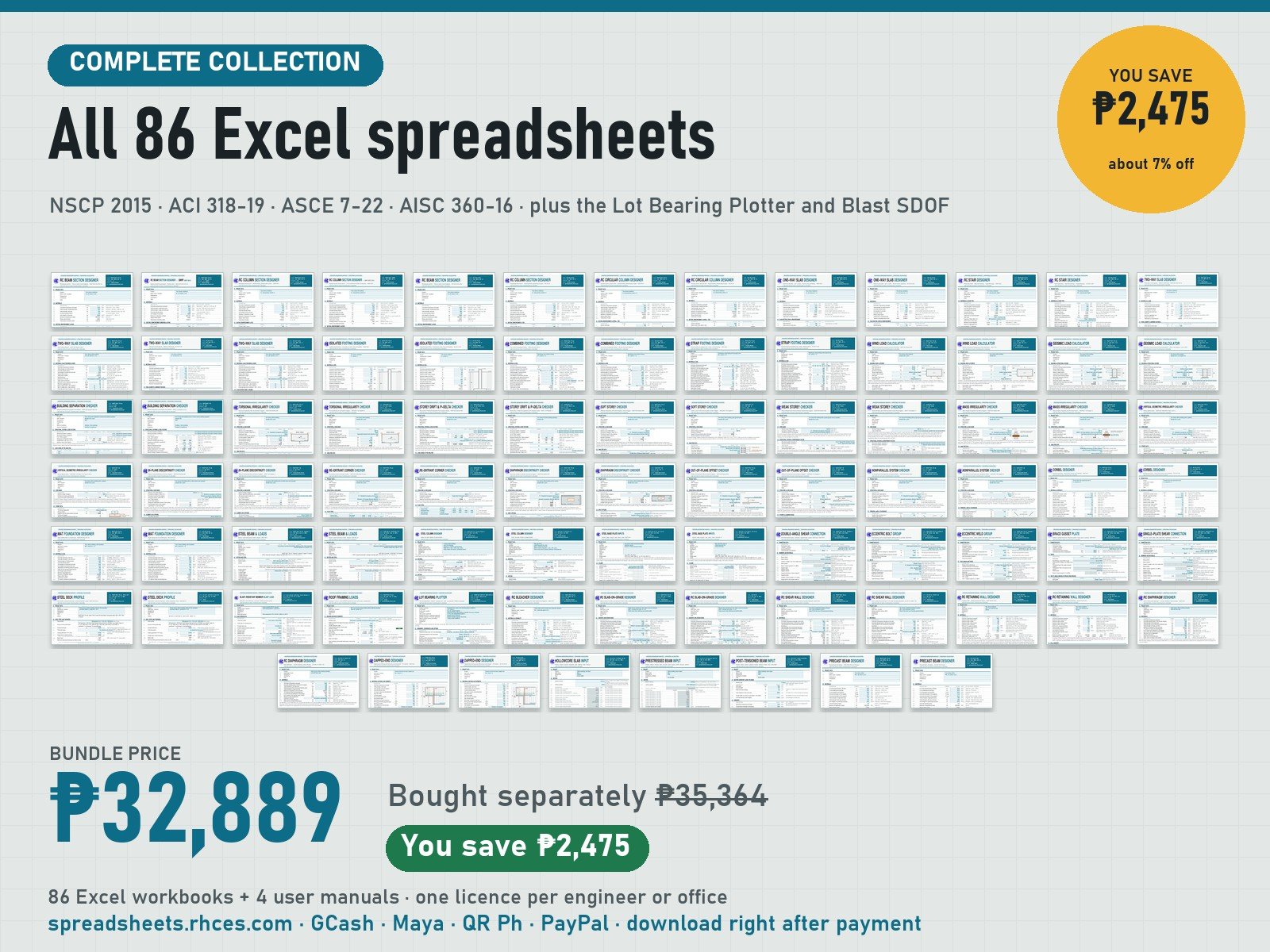
Every spreadsheet in the store in one purchase: 86 Excel design tools for NSCP 2015, ACI 318-19, ASCE 7-22 and AISC 360-16, plus the Lot Bearing Plotter, the Blast-Resistant Member Designer (SDOF) and the precast, prestressed and post-tensioned designers.
Inside: 44 NSCP 2015 designers, load calculators and checkers · 22 ACI 318-19 designers (concrete, precast, prestressed, post-tensioned, steel deck slab) · 14 ASCE 7-22 load calculators and checkers (SI units) · 4 AISC 360-16 steel designers · the Lot Bearing Plotter (land survey) and the Blast-Resistant Member Designer (SDOF).
86 Excel workbooks. Bought separately PHP 35,364; the bundle is PHP 32,889, a saving of PHP 2,475 (about 7%). Each Excel copy is licensed to the buyer's name. One licence per engineer or office.
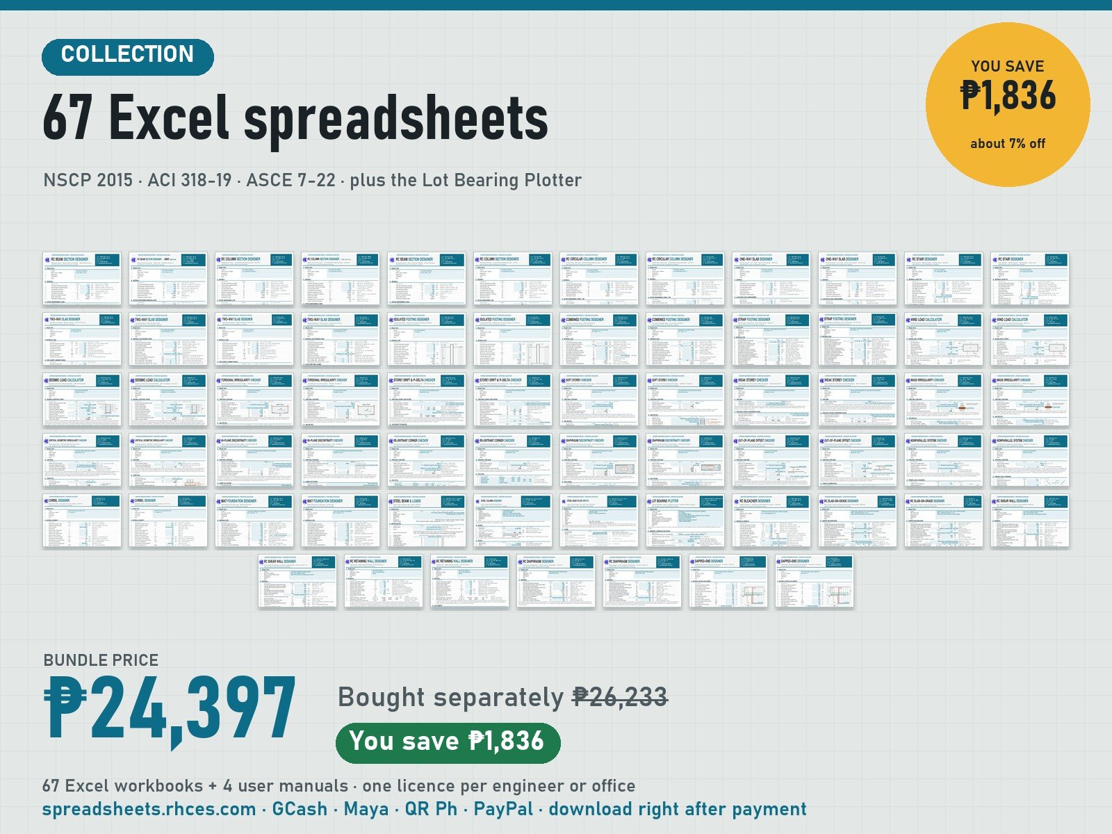
67 Excel design tools in one purchase: 36 for NSCP 2015, 30 for ACI 318-19 and ASCE 7-22, and the Lot Bearing Plotter.
Inside: 36 NSCP 2015 designers, load calculators and checkers · 30 ACI 318-19 and ASCE 7-22 designers, load calculators and checkers (SI units) · the Lot Bearing Plotter (land survey).
67 Excel workbooks. Bought separately PHP 26,233; the bundle is PHP 24,397, a saving of PHP 1,836 (about 7%). Each Excel copy is licensed to the buyer's name. One licence per engineer or office.
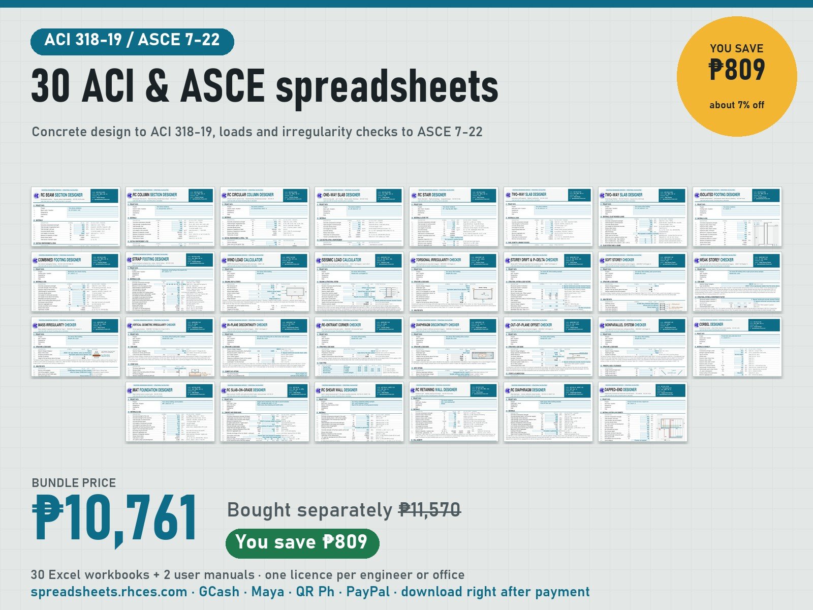
30 ACI 318-19 and ASCE 7-22 spreadsheets in one purchase (SI units): 17 reinforced-concrete and precast designers to ACI 318-19, the ASCE 7-22 wind and seismic load calculators and 11 seismic irregularity checkers.
30 Excel workbooks. Bought separately PHP 11,570; the bundle is PHP 10,761, a saving of PHP 809 (about 7%). Each Excel copy is licensed to the buyer's name. One licence per engineer or office.
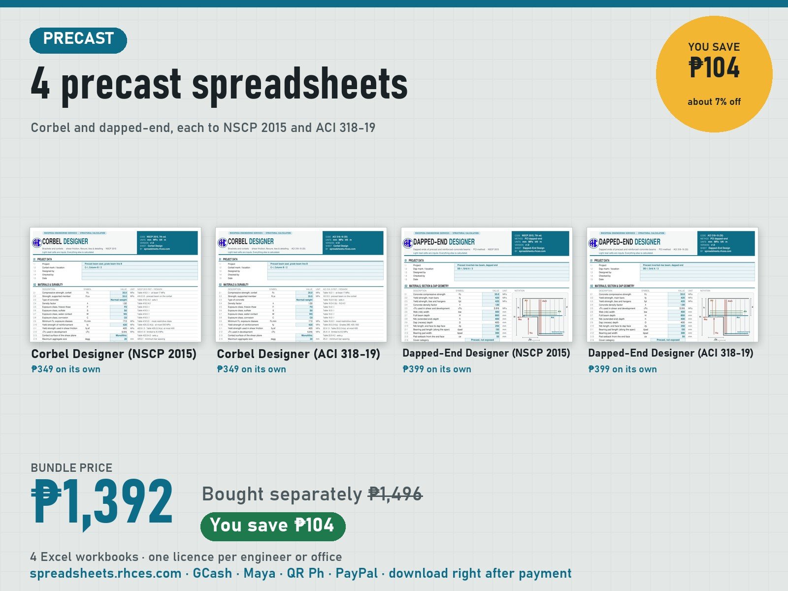
Precast Bundle: Corbel and Dapped-End, NSCP 2015 and ACI 318-19 (4 Spreadsheets)
Four precast designers in one purchase: the Corbel Designer and the Dapped-End Designer, each in two editions, NSCP 2015 and ACI 318-19 (SI units).
4 Excel workbooks. Bought separately PHP 1,496; the bundle is PHP 1,392, a saving of PHP 104 (about 7%). Each Excel copy is licensed to the buyer's name. One licence per engineer or office.
Excel · 4 Excel workbooks · 0.7 MB
Structural
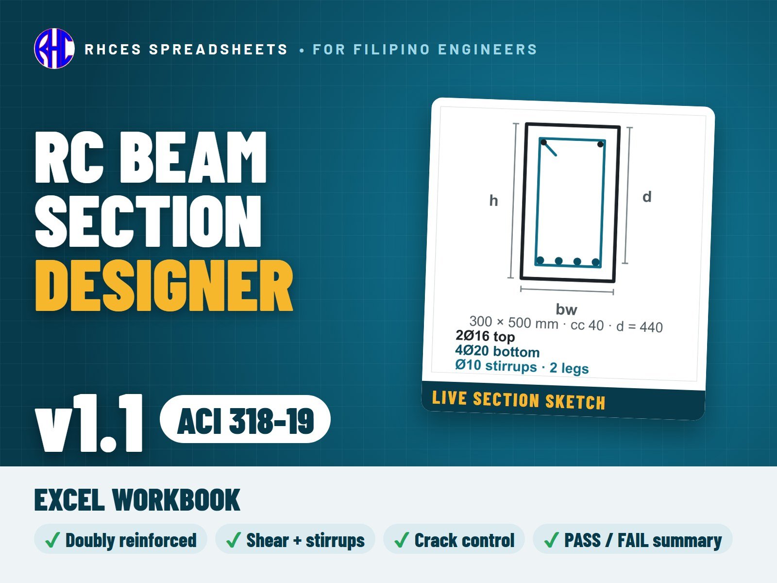
RC Beam Section Designer (ACI 318-19)
Check a rectangular reinforced-concrete beam section to ACI 318-19 (SI units) in minutes. Enter the materials, section, bars and the factored Mu and Vu, and the sheet works out the rest.
Flexure for singly or doubly reinforced beams, with tension bars placed in one or two layers automatically and the compression-steel stress found whether it yields or not. Ductility to ACI 318-19 (net tensile strain at least the yield strain + 0.003, with the matching phi), minimum steel, bar clear spacing, crack-control spacing and the minimum-depth (deflection) rule.
Shear uses the ACI 318-19 concrete shear table step by step: the simple formula, the formula with the longitudinal steel ratio, and the size-effect formula when stirrups are below the minimum, with the upper limit and a note showing which case governs. Then stirrup strength, the section limit, maximum spacing and minimum stirrups.
A design check summary shows demand, capacity, ratio and PASS / FAIL for every check, with one overall result. Every result is an open Excel formula with readable names and ACI 318-19 clause references, and it prints as a clean 3-page A4 calculation sheet.
Version 1.1 (October 2026): the section drawing is now live, redrawn from your bars and layers as you type. Results are unchanged from version 1.0. Entries outside the allowed ranges are refused, and an incomplete set of inputs shows CHECK INPUTS instead of a verdict. Bars that do not fit in their layer are drawn in red.
Includes the Excel workbook. A worked A4 sample calculation can be previewed with View sample on the store page. One licence per engineer or office. Looking for the Philippine code? See the NSCP 2015 edition.
Excel · 3-page A4 calc sheet · SI units · open formulas · v1.1
Structural
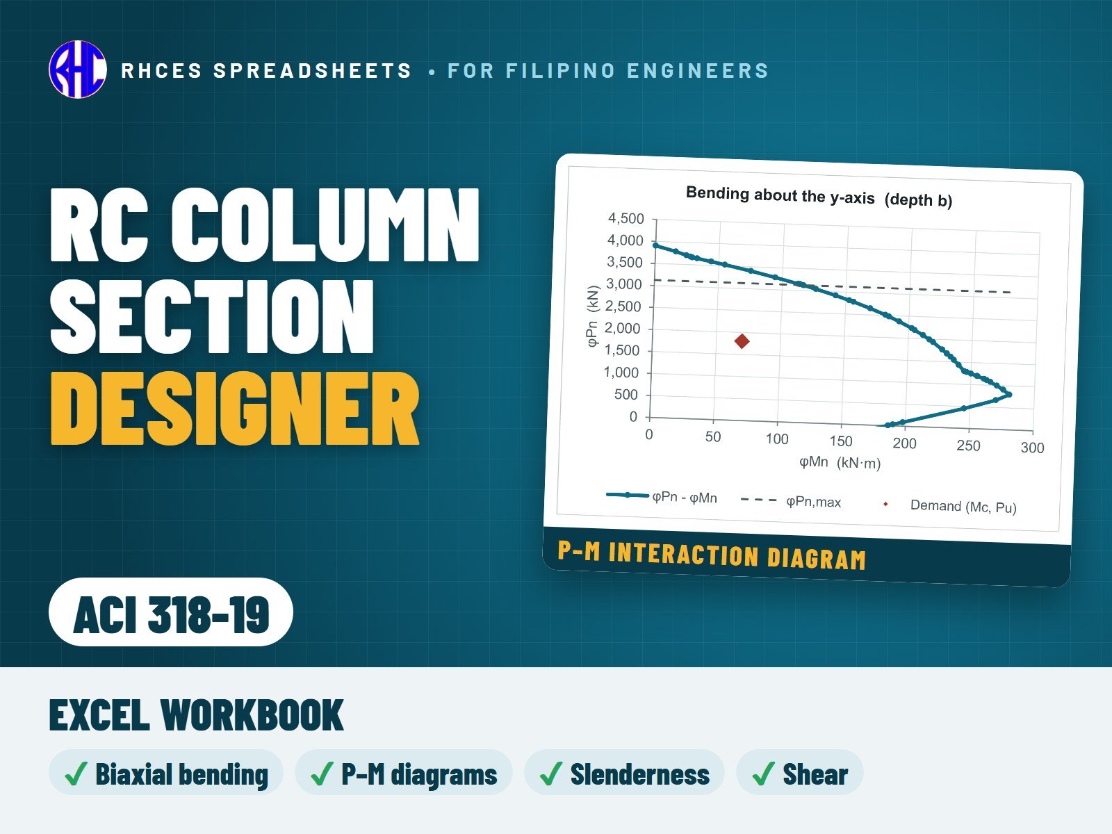
RC Column Section Designer (ACI 318-19)
Design and check a rectangular tied reinforced-concrete column to ACI 318-19 (SI units): axial load with bending about both axes, slenderness and shear, with interaction diagrams drawn for you.
The P–M interaction diagram for each axis is built by strain compatibility over every bar layer and plotted as a chart with your load point on it, using the ACI 318-19 strength reduction factors. The sheet reads the design moment capacity at your factored axial load and checks biaxial bending with the load-contour method, plus the 0.80 Po axial limit.
Slenderness per axis with moment magnification for braced columns (including the minimum moment), sway columns flagged for second-order moments, and unstable columns caught. Curvature is picked from a drop-down, so the code sign rule is applied for you.
Shear in both directions with the ACI 318-19 concrete shear table, including the axial-load term, the longitudinal-steel and size-effect formulas and the upper limit, plus minimum shear ties. Detailing checks: steel ratio 1–8 %, minimum bars, bar spacing, tie size (No. 13 for larger bars), tie spacing and crossties.
Every result is a visible Excel formula with ACI 318-19 clause references; prints as a clean A4 calculation. Ordinary (non-seismic) detailing; special moment frames (Chapter 18) are not covered in this version.
Includes the Excel workbook. A worked A4 sample calculation can be previewed with View sample on the store page. One licence per engineer or office. Looking for the Philippine code? See the NSCP 2015 edition.
Excel · A4 calc sheet + P–M interaction diagrams · SI units
Structural
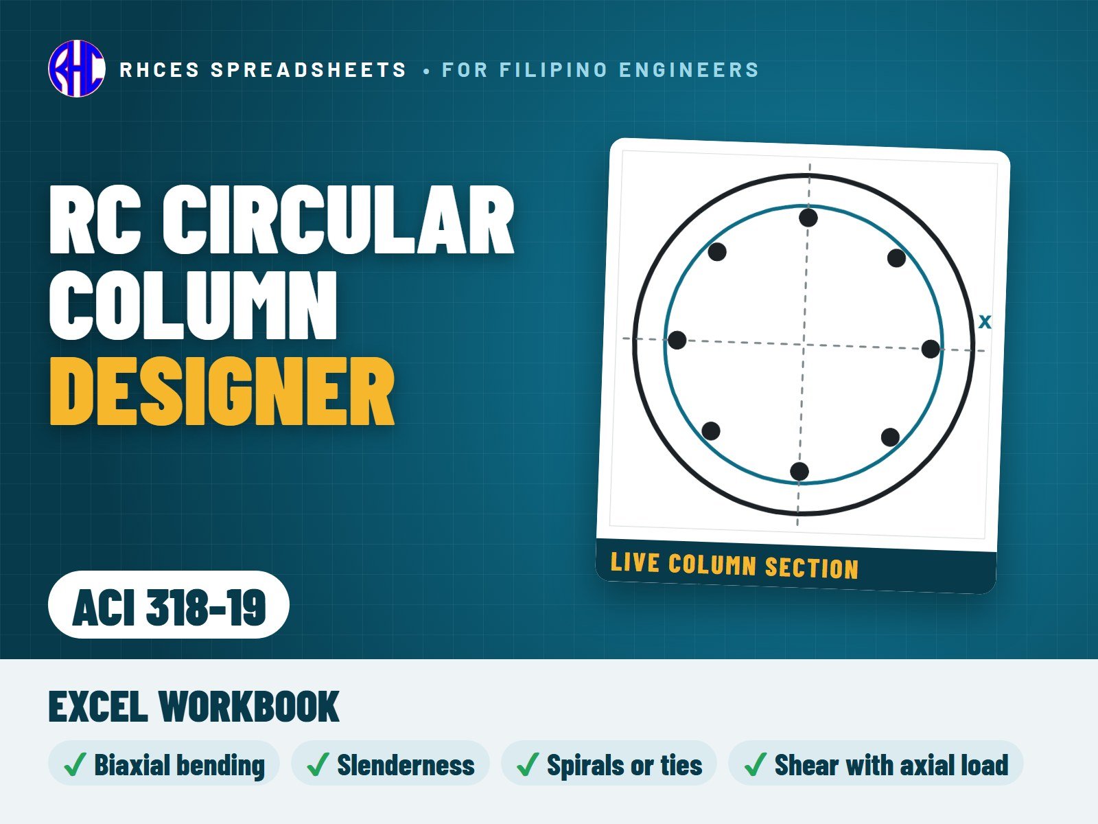
RC Circular Column Designer (ACI 318-19)
Design a solid circular reinforced-concrete column to ACI 318-19 (SI units): axial load with biaxial bending (combined as the resultant moment), slenderness and moment magnification for braced frames (with the 1.4 second-order limit), P-M interaction by strain compatibility on a circular compression zone with the bars equally spaced on one circle, shear with axial load, and the longitudinal-bar, spiral and circular-tie detailing limits of Chapters 10 and 25, with the ACI 318-19 phi transition and the Table 22.5.5.1 shear strength.
Enter the diameter, cover, materials, bars and the factored loads (several load rows); the sheet draws the live P-M interaction diagram with your load points, checks capacity, spiral or tie size and pitch, bar spacing and cover, and gives one overall result. Companion to the RC Column Section Designer (rectangular).
Every result is a visible Excel formula with ACI 318-19 section references. Includes the Excel workbook. A worked A4 sample calculation can be previewed with View sample on the store page. One licence per engineer or office. Looking for the Philippine code? See the NSCP 2015 edition.
Excel · A4 calc sheet + P–M interaction diagram · SI units
Structural
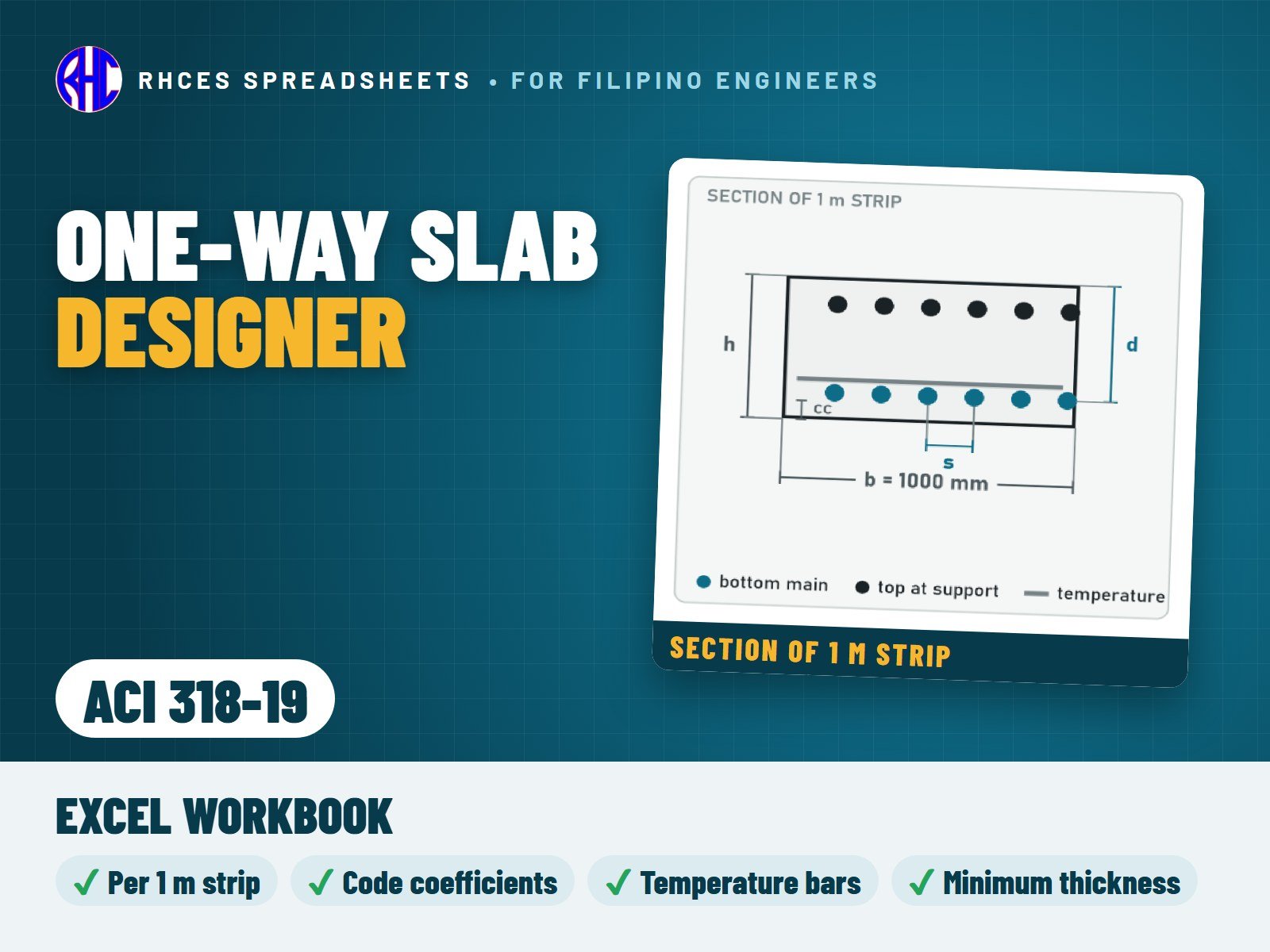
One-Way Slab Designer (ACI 318-19)
Design a solid one-way reinforced-concrete slab to ACI 318-19 (SI units) per 1 m strip, from loads to bar spacing.
Self-weight is worked out for you; the factored load uses the larger of 1.4D and 1.2D + 1.6L. Moments and shear come from your choice: simply supported, cantilever, the ACI approximate coefficients for continuous slabs (all positive and negative locations, with the 1.15 shear factor), or values from your own analysis.
Checks bottom and top bars for strength and the ACI 318-19 tension-controlled limit, minimum and temperature steel (0.0018 Ag), maximum spacing, crack control and clear spacing; one-way shear with the ACI 318-19 size-effect formula (no stirrups); and minimum thickness for deflection. Design aids give the required steel and the largest bar spacing that works.
Every result is a visible Excel formula with ACI 318-19 clause references. Includes the Excel workbook. A worked A4 sample calculation can be previewed with View sample on the store page. One licence per engineer or office. Looking for the Philippine code? See the NSCP 2015 edition.
Excel · 2-page A4 calc sheet · per 1 m strip · SI units
Structural
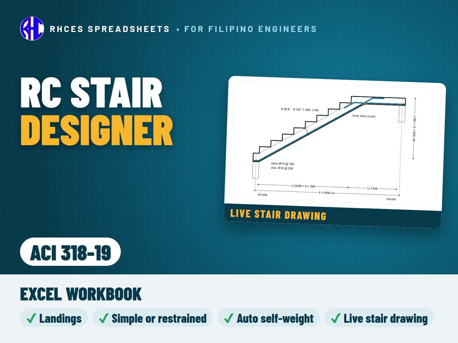
RC Stair Designer (ACI 318-19)
Design a reinforced-concrete waist-slab stair to ACI 318-19 (SI units): a straight flight, or a flight with a landing at the bottom, at the top or at both ends, spanning along the flight between simple or restrained supports.
Enter the number of risers, the rise and tread, the landing lengths, the support widths, the materials, the bars and the loads (finishes, soffit, live load and an optional tread load). The sheet works out the self-weight of the waist and steps and the factored load, then the moments and shear: exact statics for simply supported flights, the ACI 318 6.5 coefficients for restrained ends, or your own moments. It checks flexure with the effective depth perpendicular to the slope, ductility, minimum and distribution steel, bar spacing and crack control, cover, shear without stirrups by Table 22.5.5.1 (with the size effect), the minimum thickness for deflection, and the development and anchorage of the bars at the supports. It flags the re-entrant kink where a flight meets a landing above it and shows the crossing-bar detail, and gives editable riser, tread, 2R + T and headroom guidance lines.
A live drawing shows the steps, waist, landings, supports and every bar group. The check summary gives demand, capacity, ratio and PASS / FAIL for every line, with one overall result. Cross-checked against a published university stair example (within 0.3 %).
Not covered: cantilever, helical and free-standing stairs, precast stairs and flights with an intermediate support.
Every result is a visible Excel formula with ACI 318-19 section references. Includes the Excel workbook. A worked A4 sample calculation can be previewed with View sample on the store page. One licence per engineer or office. Looking for the Philippine code? See the NSCP 2015 edition.
Excel · 4-page A4 calc sheet + live stair drawing · SI units
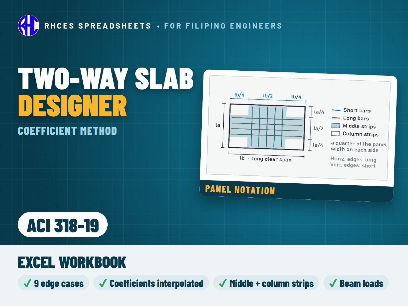
Design a two-way slab panel supported on beams or walls on all four edges with the classic moment and shear coefficient method (ACI 318-63 Method 3), with the bars and checks to ACI 318-19 (SI units).
Pick one of the 9 edge-condition cases (sketches included), enter spans, thickness, loads and bars, and the sheet interpolates every coefficient for your span ratio: middle-strip negative and positive moments both ways, discontinuous-edge moments and column-strip values.
Checks each bar layer for strength and the ACI 318-19 tension-controlled limit, minimum steel (0.0018 Ag), maximum spacing, clear spacing, shear at every edge with the ACI 318-19 size-effect formula, and minimum thickness. It also gives the load carried to each supporting beam. The coefficient tables were cross-checked against three independent sources, including scans of the original ACI 318-63 tables.
Every result is a visible Excel formula with ACI 318-19 clause references. Includes the Excel workbook. A worked A4 sample calculation can be previewed with View sample on the store page. One licence per engineer or office. Looking for the Philippine code? See the NSCP 2015 edition.
Excel · A4 calc sheet + full coefficient tables · SI units
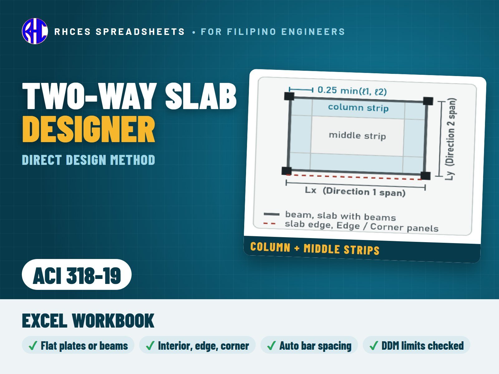
Design a two-way slab system with the Direct Design Method of ACI 318-19 Section 8.10 (SI units): flat plates (with or without an edge beam) and slabs with beams between all supports, for interior, edge and corner panels, both directions side by side.
Checks the DDM limitations, works out Mo, distributes it along the span and between column strips, middle strips and beams with the code tables (beam stiffness and torsion from your beam sizes), and sizes the bars automatically for every strip location, including the new ACI 318-19 minimum top steel at columns where punching stress is high (8.6.1.2).
Also checks minimum thickness, one-way shear and punching shear with the ACI 318-19 size effect and moment transfer at interior and edge columns (0.3 Mo at edge columns). Corner-column punching is not covered in this version.
Every result is a visible Excel formula with ACI 318-19 clause references. Includes the Excel workbook. A worked A4 sample calculation can be previewed with View sample on the store page. One licence per engineer or office. Looking for the Philippine code? See the NSCP 2015 edition.
Excel · A4 calc sheet + DDM tables · auto bar spacing · SI units
Structural
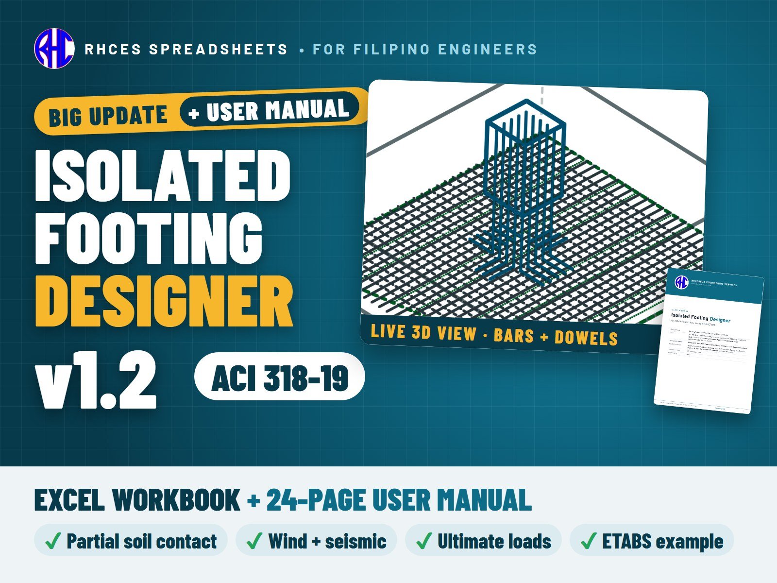
Isolated Footing Designer (ACI 318-19)
Design an isolated (spread) footing under a rectangular column to ACI 318-19 (SI units), square or rectangular, from service loads to bars.
Enter the column, the dead and live axial loads (moments optional), the soil data and a trial footing. The sheet works out the net allowable soil pressure, the service pressure with moments and the full-contact (kern) check, and the factored soil pressure used for design.
Checks one-way shear in both directions, punching shear at d/2 including the shear from column moments, flexure at the column face both ways, minimum steel, the central-band rule for rectangular footings, bar spacing, development length of the bottom bars, column bearing, dowels and dowel development. Design aids suggest a square footing size and the bar spacing you need. A live footing plan shows the column, the critical sections, the steel band and where the load acts.
ACI 318-19 specifics: one-way shear with the Table 22.5.5.1 formula, a switch for the size-effect factor (13.2.6.2 lets you neglect it for footings), the 8.6.1.2 minimum steel near the column, minimum steel 0.0018 Ag and the εty + 0.003 ductility limit.
Every result is a visible Excel formula with ACI 318-19 clause references. Includes the Excel workbook and a 24-page user manual (A4 PDF) that takes a real ETABS 22.7 model step by step: the Joint Reactions of column C7 of a 3-storey residential building, the inputs, the load combinations, the results, partial contact and the Ultimate Loads mode. A worked A4 sample calculation can be previewed with View sample on the store page. One licence per engineer or office. Looking for the Philippine code? See the NSCP 2015 edition.
Version 1.1: column offset incl. edge and corner columns, live plan and elevation sketches with forces, live footing section.
Version 1.2: partial soil contact when e > L/6, wind and seismic ASCE 7 / IBC load combinations with an optional allowable increase (%), labelled load combinations, an Ultimate Loads input for the governing factored combination, and a live 3D view of the footing with rebar.
Excel · 5-page A4 calc sheet + live footing plan · SI units · v1.2 · 2 files incl. user manual
Includes 2 files: Excel workbook: Isolated Footing Designer, ACI 318-19 · User manual, A4 (24 pages)
Structural
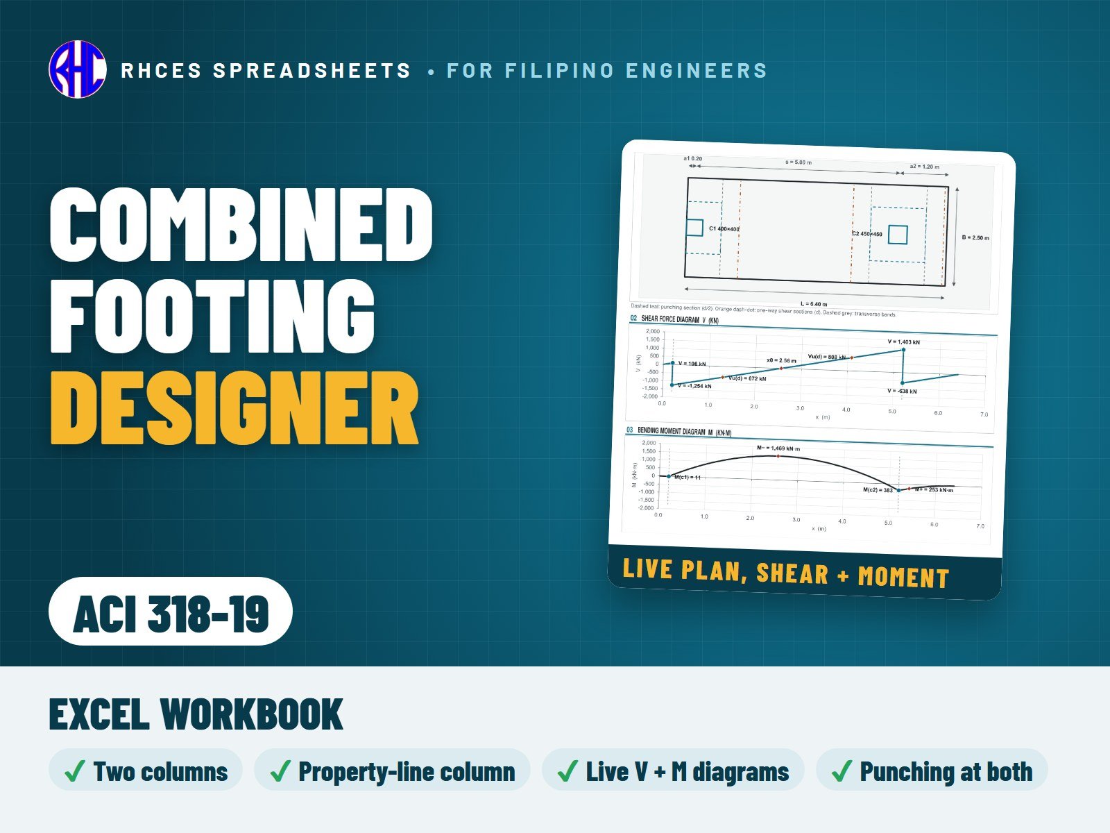
Combined Footing Designer (ACI 318-19)
Design a rectangular combined footing carrying two columns to ACI 318-19 (SI units), including an exterior column right at the property line.
The sheet sizes the footing length so the soil pressure is uniform (load resultant at the centre), or checks a length you enter with the trapezoidal pressure and the kern check. The footing is then designed as a beam along its length, with live shear-force and bending-moment diagrams: the largest negative moment between the columns sets the top bars, the moments at the column faces set the bottom bars.
Checks one-way shear at d from the column faces, punching at both columns (a three-sided edge section for a column at the property line), flexure and ductility of the top and bottom bars, transverse bands under each column, minimum steel, spacing, development length (top-bar factor applied), column bearing and dowels. A live plan drawing shows the columns, critical sections and transverse bands. Gravity loads; moment transfer at the columns is not included in this version.
ACI 318-19 specifics: one-way shear with the Table 22.5.5.1 formula, a switch for the size-effect factor (13.2.6.2 lets you neglect it for footings), minimum steel 0.0018 Ag and the εty + 0.003 ductility limit.
Every result is a visible Excel formula with ACI 318-19 clause references. Includes the Excel workbook. A worked A4 sample calculation can be previewed with View sample on the store page. One licence per engineer or office. Looking for the Philippine code? See the NSCP 2015 edition.
Excel · A4 calc sheet + live plan, shear & moment diagrams · SI units
Structural
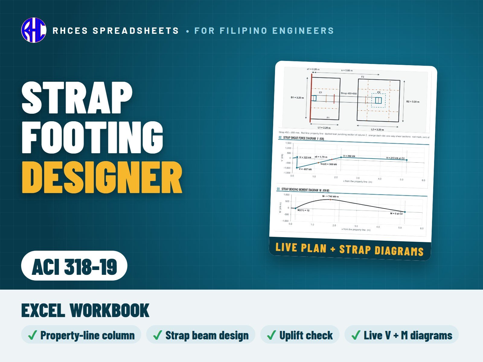
Strap Footing Designer (ACI 318-19)
Design a strap (cantilever) footing to ACI 318-19 (SI units): an exterior column at the property line on its own footing, tied by a strap beam to an interior column on a concentric footing, so the soil pressure stays uniform under both.
The sheet solves the statics for the two footing reactions (strap self-weight optional), sizes the footings from the allowable soil pressure, and lets you design the interior footing for the full column load (default, conservative) or the reduced reaction. It checks uplift on the interior footing.
Strap beam: live shear and bending-moment diagrams, top steel for the maximum moment, minimum bottom steel and any sagging, ductility, stirrups (Vc by Table 22.5.5.1, Vs, maximum spacing, minimum shear steel, section limit) and anchorage of the top bars at the property-line end. Exterior footing: designed across as cantilevers from the strap faces, with one-way shear, flexure, steel both ways, spacing and development. Interior footing: punching (with the optional size effect), one-way shear and flexure both ways, central band, the flexure-driven punching steel of 8.6.1.2, development. Column bearing and dowels for both columns. A true-scale plan shows the property line, both footings, the strap and the critical sections. Gravity loads.
Every result is a visible Excel formula with ACI 318-19 section references. Includes the Excel workbook. A worked A4 sample calculation can be previewed with View sample on the store page. One licence per engineer or office. Looking for the Philippine code? See the NSCP 2015 edition.
Excel · A4 calc sheet + live plan, strap shear & moment diagrams · SI units
Precast
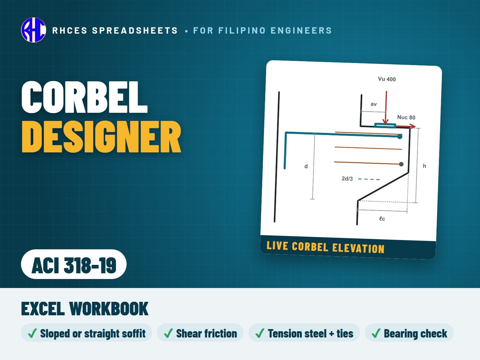
Corbel Designer (ACI 318-19)
Design a reinforced-concrete column corbel or bracket (sloped or straight soffit) by the traditional method of ACI 318-19 Section 16.5 (SI units): the applicability limits (av/d, Nuc not above Vu, outside depth, bearing area against the tie anchorage), the limit on Vn, shear friction, flexure with direct tension, the primary tension steel Asc and the closed ties Ah, bearing under the plate, cover, bar spacing and development at the column face, plate set-back and bearing of the lesser surface.
Enter the corbel geometry, the bearing plate, the materials, Vu and Nuc (or let the sheet take the minimum tension) and the bars; it reports every check with demand, capacity, ratio and PASS / FAIL, a live elevation of the corbel with the bars, and one overall result. Strut-and-tie design is out of scope (the Read Me says where it applies).
Every result is a visible Excel formula with ACI 318-19 section references. Includes the Excel workbook. A worked A4 sample calculation can be previewed with View sample on the store page. One licence per engineer or office. Looking for the Philippine code? See the NSCP 2015 edition.
Excel · A4 calc sheet + live corbel elevation · SI units
Structural
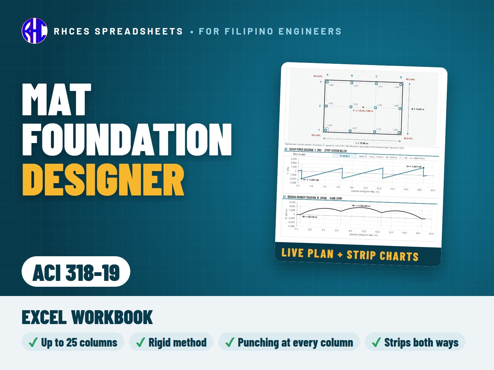
Mat Foundation Designer (ACI 318-19)
Design a rectangular mat (raft) foundation of uniform thickness under a regular grid of columns (2 to 5 column lines each way, up to 25 columns) by the conventional rigid method (ACI 336.2R; Das; Bowles) to ACI 318-19 (SI units): rigidity check, soil pressure under service and factored column loads from the resultant, punching shear at every column (interior, edge and corner sections, cut by the mat edge when the overhang is short) with the flexure-driven punching steel of 8.6.1.2, the strip method in both directions with the load / reaction adjustment, shear and moment of every strip as live tables and charts, one-way shear in the strips, top and bottom reinforcement both ways per metre, spacing, development and column bearing.
Enter the mat size and thickness, the column grid and loads, the soil pressure and the materials; the sheet draws the plan with the strips and reports every check with PASS / FAIL and one overall result.
Every result is a visible Excel formula with ACI 318-19 section references. Includes the Excel workbook. A worked A4 sample calculation can be previewed with View sample on the store page. One licence per engineer or office. Looking for the Philippine code? See the NSCP 2015 edition.
Excel · A4 calc sheets + live plan, strip shear & moment charts · SI units
Steel
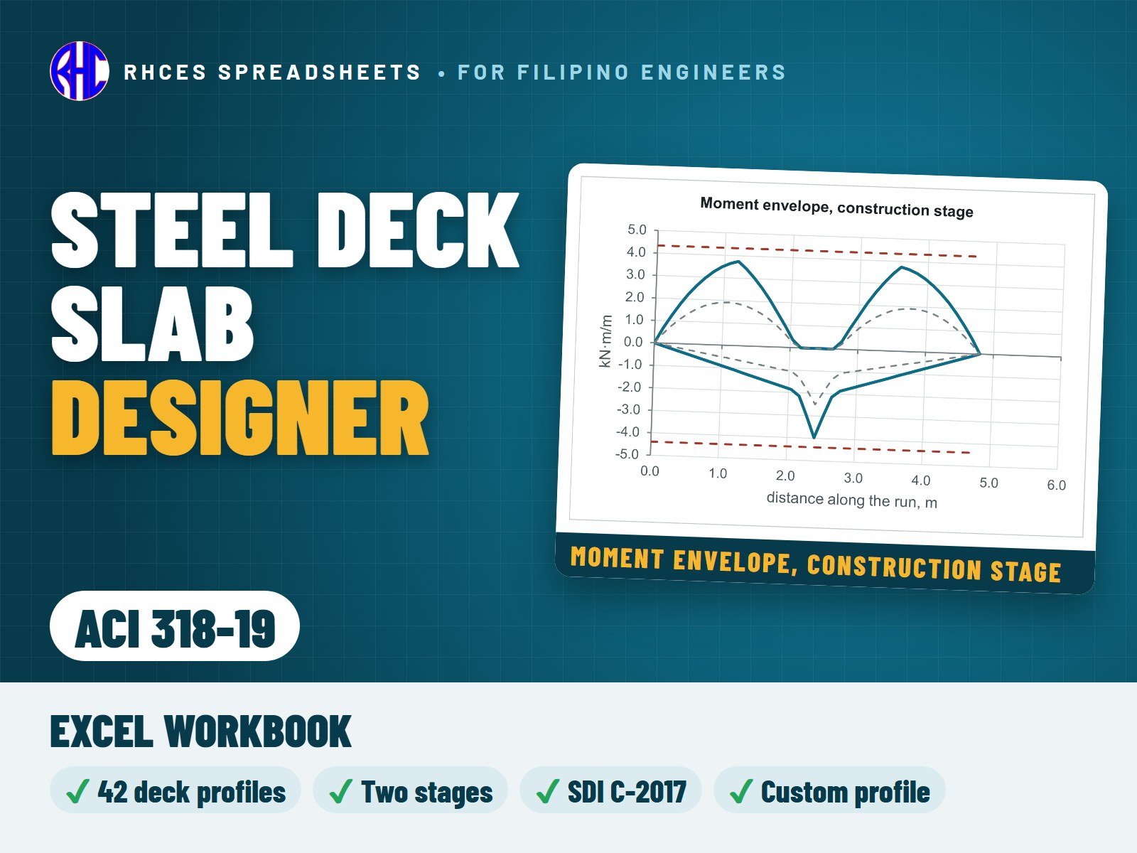
Steel Deck Slab Designer (ACI 318-19)
Design one composite steel deck slab panel (one deck run) in two stages: the composite slab and the construction loads by ANSI/SDI C-2017, the deck as cold-formed steel by AISI S100-16, and the concrete and reinforcement by ACI 318-19 (SI units, loads by ASCE 7-16). Pick the deck from the library (42 rows: SDI generic profiles, ASC Steel Deck, Philmetal Products and Steeltech) or type a Custom profile from the maker's drawing, with the steel, the thickness and its basis (base metal or total coated). The deck library values are marked P (published), C (computed) or N (not published) with the document read in October 2026; they are not maker-verified, so confirm them against the maker's current catalogue before use.
Stage 1, the deck as a form while the concrete is placed: the SDI construction load cases on one to four or more spans, equal or unequal, with an optional end cantilever and optional or automatic shoring; deck flexure, shear, web crippling and their interactions, deflection, the maximum unshored span and the shore-line loads. LRFD, with ASD offered for this stage.
Stage 2, the hardened composite slab: flexure by the SDI Prequalified Section Method or the maker's declared strength (or, by choice, a reinforced concrete slab on the deck as a form only), one-way shear, deflection, a concentrated load (effective width, punching, weak-axis steel), temperature and shrinkage steel, top bars over the beams of a continuous slab, and the bars, shear and service deflection of an end cantilever. The deck items the beam designer needs (rib height and width, concrete above the deck, stud diameter and length, stud height above the deck, cover over the stud, deck anchorage) are listed against the AISC 360-16 stud and rib limits. Drawings redraw from your inputs: the deck profile, and the construction-stage spans with the moment envelope and deflection. The Design Check Summary collects every check under one overall result: STEEL DECK SLAB ADEQUATE, ADEQUATE · SEE CHECKS, REVISE THE DECK OR THE SLAB or INCOMPLETE DATA · SEE CHECKS.
Not covered: diaphragm design, fire rating, floor vibration, the composite beam itself (studs and beam strength; only the deck items are listed), SDI Appendix 3 (shear bond, needs the maker's test values) and Appendix 4 (ultimate strength with studs), C-2017 A2.2.2 (over-reinforced slabs, not implemented; the check is conservative), ASD for the composite stage, two-way slabs on deck, cellular, re-entrant and flat-pan decks, roof decks without concrete, openings and edge trims, and live-load reduction. The Read Me lists the items worth confirming.
References: ANSI/SDI C-2017 for the composite slab and the construction loads; AISI S100-16 w/ S3-22 for the deck; ACI 318M-19 for the concrete and reinforcement (ACI 318-19 excludes composite deck slabs, 1.4.10, so SDI governs them); ASCE 7-16 for the loads; also the SDI Floor Deck Design Manual 2nd ed., AISC 360-16 (I3.2c, I8.1) and ASCE/SEI 37-14, with the printed page of each reference shown in the workbook. NSCP 2015 is not used in this edition.
The method was checked against the worked examples of the SDI Floor Deck Design Manual (construction spans, unequal spans, composite section, shear and concentrated load) and against maker catalogue tables, and every number was compared with a second, independent calculation.
Every result is a visible Excel formula with the clause and page of each reference. Includes the Excel workbook. View sample on the store page previews a worked A4 sample calculation (17 pages: a 2nd-floor office slab on SDI generic 2 in. x 12 in. deck, 0.91 mm, over two 2.50 m spans, 125 mm slab, f'c 21 MPa; result STEEL DECK SLAB ADEQUATE, governed by deck web crippling at the interior beam while the concrete is placed). One licence per engineer or office.
Excel · Deck, Construction Stage, Composite Slab, Reinforcement and Summary sheets (A4); View sample: 17 pag
Structural
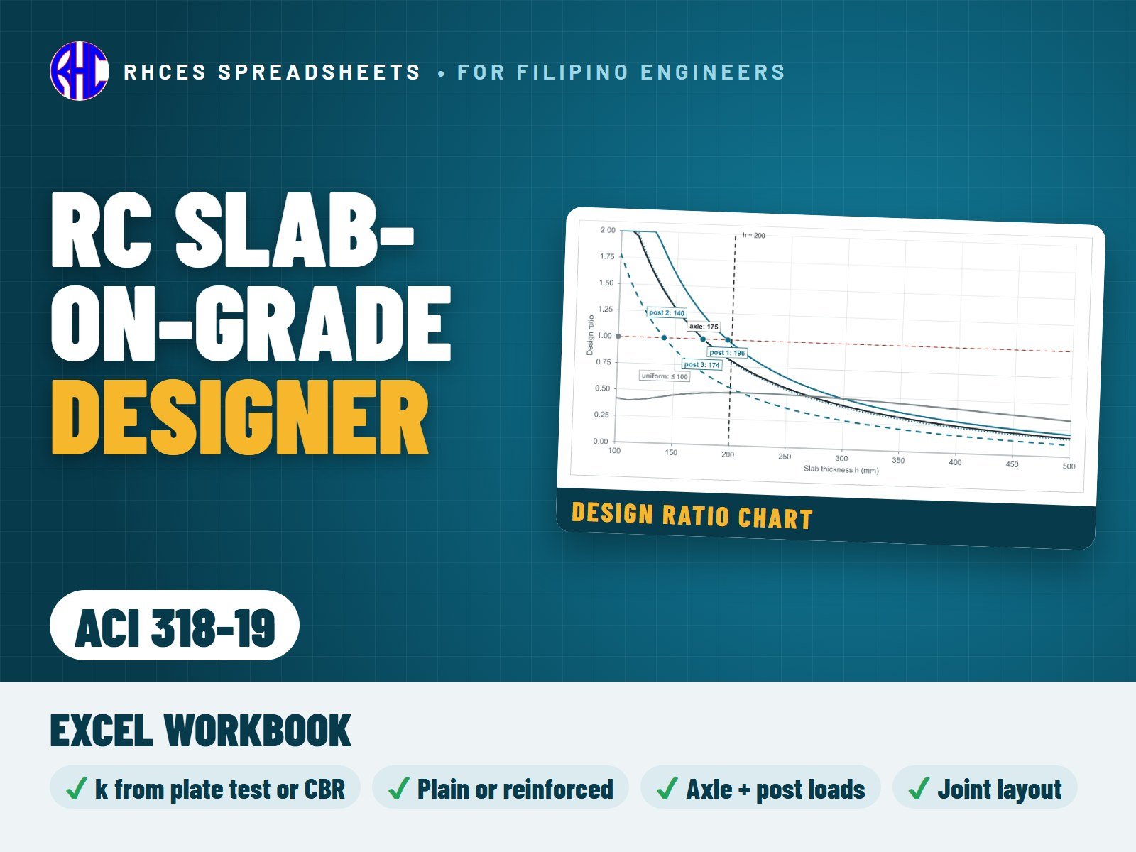
RC Slab-on-Grade Designer (ACI 318-19)
Design one concrete slab on ground (slab-on-grade) of uniform thickness for a warehouse, industrial, commercial or residential floor, on a subgrade with an optional granular sub-base (SI units). ACI 318-19 1.4.8 exempts floor slabs on ground that carry no loads from the structure (R1.4.8 points to ACI 360R), so the thickness comes from the published methods with service loads and safety factors, while ACI 318-19 supplies the concrete, durability, cover, spacing, laps, punching and bearing rules. Subgrade k from a plate load test, CBR or soil type, with the composite k on top of the sub-base. Plain slabs with sawcut joints, or one or two layers of distributed steel; dowelled, aggregate-interlock or free-edge joints.
Loads: one forklift or vehicle axle (from the rated capacity, service weight and axle share, or typed; single or dual wheels; solid or pneumatic tyres; load repetitions for the fatigue safety factor), up to 4 rows of rack posts or point loads (back-to-back racks as a 2 × 2 post group, single racks or single posts, at a joint or not) and one uniform storage load with a fixed or variable aisle layout.
Wheels and posts by PCA (default), Westergaard and Meyerhof, all three side by side, the chosen one driving the statuses; flexural strength from the code modulus of rupture 0.62√f'c by default, or a tested value. Checks: flexure in the interior and at joints for each load and the thickness each case needs; the uniform-load aisle moment (Hetenyi) and soil pressure; punching shear around base plates and tyres by the code equations (Table 14.5.5.1, or 22.6.5.2 with the size factor for two layers) with combined perimeters for close loads; bearing; joint spacing, sawcut depth and dowels; distributed steel by subgrade drag and the 0.1 % minimum, cover, spacing and laps. A switch for a slab that carries loads from the structure or acts as a tie adds the code plain-concrete checks under factored loads.
Live drawings show the slab section at a joint, the axle and post-group plans with punching perimeters, the design ratio against slab thickness and the joint layout; the 33-line summary reports demand, capacity, ratio and PASS / FAIL / CHECK, with the required thickness and one overall result. Not covered: fibre-reinforced, post-tensioned, jointless and pile-supported slabs, slabs carrying columns or walls, line and wall loads, multi-axle trucks, mixed-traffic fatigue, curling analysis, dowel capacity, expansive soils and settlement. The Read Me lists the items taken from a single published source that are worth confirming.
Every result is a visible Excel formula, with ACI 318-19 section references for the code items. Includes the Excel workbook. A worked A4 sample calculation can be previewed with View sample on the store page. One licence per engineer or office. Looking for the Philippine code? See the NSCP 2015 edition.
Excel · A4 calc sheets + live slab section, axle & post plans, ratio chart & joint layout · SI units
Structural
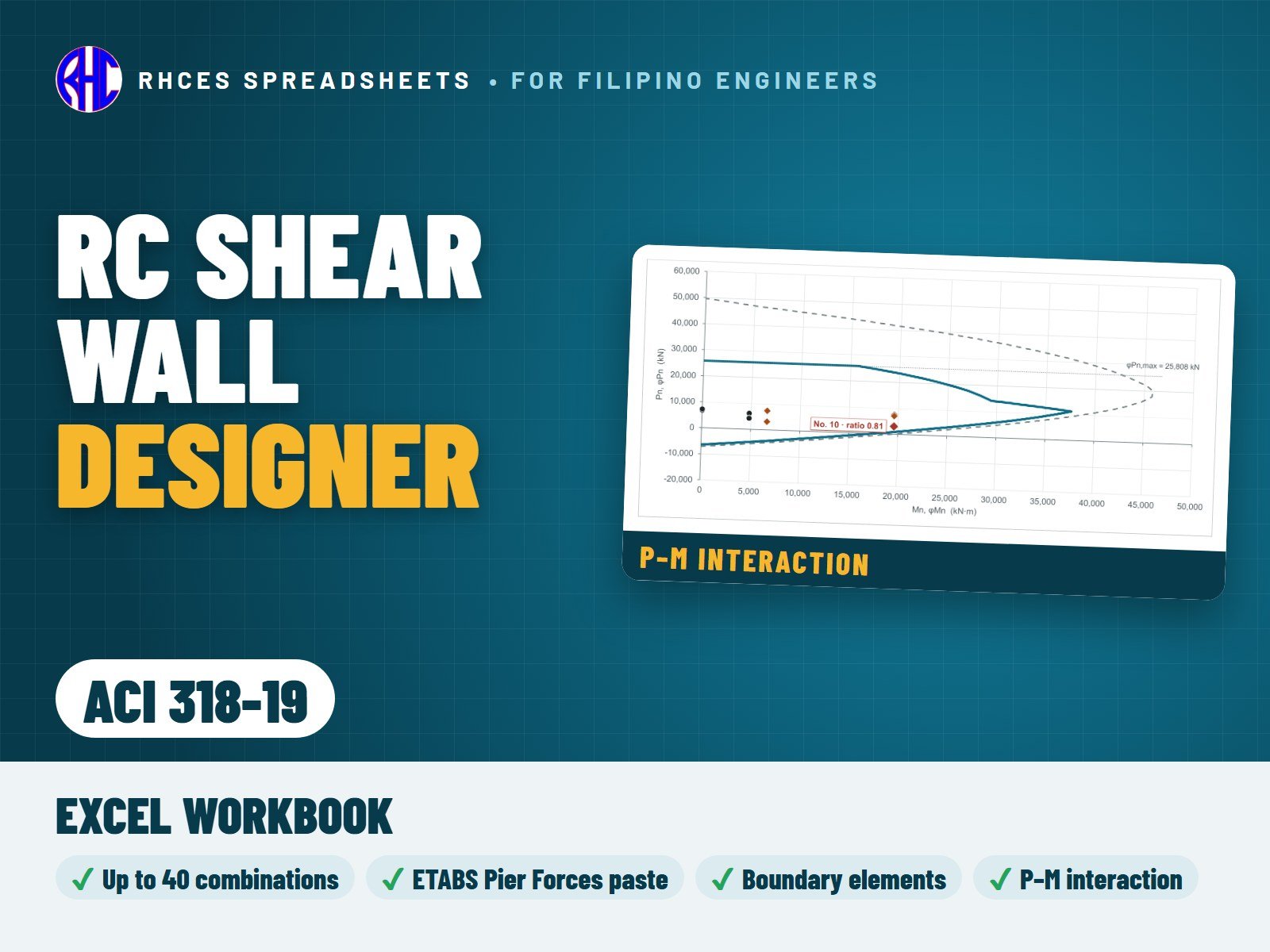
RC Shear Wall Designer (ACI 318-19)
Design one section of a cast-in-place reinforced-concrete structural (shear) wall at a time, usually the critical section at the base, to ACI 318-19 Chapter 11 and, for special structural walls, 18.10, with the seismic basis of ASCE 7-22 (SI units): rectangular, with web bars in one or two curtains and optional boundary zones at both ends. Type the factored Pu, Mu and Vu of up to 40 combinations or paste the ETABS Pier Forces table (ETABS 22 or older layouts). The top displacement for the boundary-element check is typed from your analysis.
P-M interaction by strain compatibility for every combination, with the probable moment Mpr. Checks: in-plane shear (special walls: Ve = Ωv ωv Vu not above 3 Vu, 18.10.3.1, with one Ωv for the wall per note [1] of Table 18.10.3.1.2) and its limit; the need for special boundary elements, displacement-based with the drift capacity check (18.10.6.2) or stress-based (18.10.6.3), and their extent, width, Ash, spacing, hx, hoop legs, web crossties and floor concrete (18.10.6.4) and height, or the boundary ties of 18.10.6.5; minimum web steel, end reinforcement (18.10.2.4), curtains and spacing; shear friction and joint roughening; development and Class B laps, the no-lap zone above the critical section (18.10.2.3(c)) and a flag for the Ktr rule of 25.4.2.2 and 25.5.1.5 on Grade 550 and 690 bars spaced closer than 150 mm.
Live drawings show the plan section, the boundary element, the elevation and the P-M diagram with every combination; the 48-line summary reports demand, capacity, ratio and PASS / FAIL, with one overall result. Rectangular, symmetrically reinforced walls only, with the same boundary zone (or none) at both ends: flanged, C, L and barbell walls, openings, coupling beams, wall piers (screened only) and out-of-plane design are not covered. The ASCE 7-22 items follow published secondary sources; the Read Me lists them and what is still to be confirmed.
Every result is a visible Excel formula with ACI 318-19 section references. Includes the Excel workbook. A worked A4 sample calculation can be previewed with View sample on the store page. One licence per engineer or office. Looking for the Philippine code? See the NSCP 2015 edition.
Excel · A4 calc sheets + live plan section, boundary element, elevation & P-M diagram · SI units
Structural
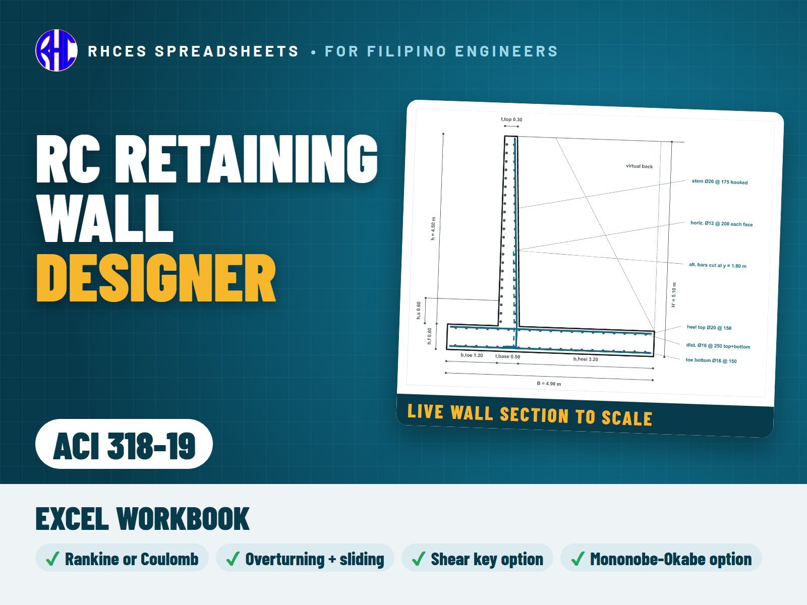
RC Retaining Wall Designer (ACI 318-19)
Design a cantilever reinforced-concrete retaining wall per metre run to ACI 318-19 (SI units): battered stem, level or sloping backfill, surcharge, soil over the toe and an optional reinforced shear key. Earth pressure by Rankine or Coulomb, with a minimum fluid pressure for a level backfill that you set.
Stability under service loads with your factors of safety: overturning, sliding (friction, adhesion, passive and key), the resultant in the middle third, bearing pressure and Meyerhof bearing capacity, plus an optional Mononobe-Okabe seismic check for both signs of kv. The stem, heel, toe and key are designed for Table 5.3.1 with 1.6H: flexure (tension-controlled), one-way shear by Table 22.5.5.1 with the size effect (which 13.2.6.2 lets you neglect in the footing), minimum steel 0.0018 Ag, crack control, clear spacing, cover, development and hooks, the 25.4.2.2 rule for fy 550 MPa bars, shear friction at the stem-footing joint and the cut-off of alternate stem bars.
A to-scale wall section redraws itself as you type, and the 53-line summary reports demand, capacity, ratio and PASS / FAIL for every check, with one overall result. Basement (at-rest) walls, water pressure, settlement and global stability are not covered.
Every result is a visible Excel formula with ACI 318-19 section references. Includes the Excel workbook. A worked A4 sample calculation can be previewed with View sample on the store page. One licence per engineer or office. Looking for the Philippine code? See the NSCP 2015 edition.
Excel · A4 calc sheets + live to-scale wall section · SI units
Structural
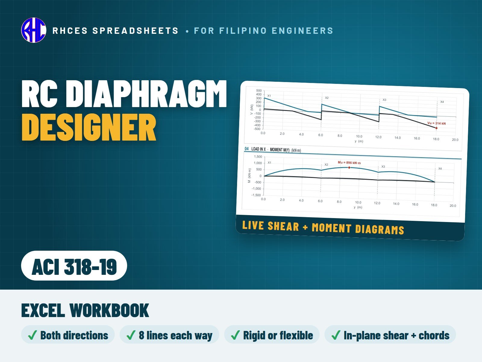
RC Diaphragm Designer (ACI 318-19)
Design a cast-in-place reinforced-concrete floor or roof diaphragm (solid slab of uniform thickness) in both plan directions by the beam analogy of ACI 318-19 Chapter 12 and the seismic rules of 18.12, with the diaphragm forces of ASCE 7-22 12.10 (SI units): a rectangular plan with up to 8 lines of walls or frames each way and one opening, with storey forces for up to 50 levels worked out from the base shear and period, or typed.
Fpx by Eq. 12.10-1 within the limits of 12.10-2 and 12.10-3 (or typed), plus wind and transfer forces; line reactions by a flexible, rigid (with torsion) or envelope model, with live shear and moment diagrams. Checks: in-plane shear and its limit, chords, collectors by the force sets of 12.10.2.1 with Ωo and the Exception 1 cap (tension, compression, the average tensile stress of 18.12.7.5, the stress limit and hoops of 18.12.7.6, splice zones), shear friction with roughened joints in SDC D to F, collector extension, development and Class B laps (with 25.4.2.2), minimum thickness, minimum slab steel and bar spacing, and the net section, chords, trimmers and drag bars at the opening.
A live plan shows the lines, collectors, chords and opening; the 66-line summary reports demand, capacity, ratio and PASS / FAIL for every check, with one overall result. Precast, prestressed and non-rectangular diaphragms, the gravity (out-of-plane) design of the slab and the combined axial force and gravity moment of beam collectors are not covered. The ASCE 7-22 items follow published secondary sources; the Read Me lists them and what is still to be confirmed.
Every result is a visible Excel formula with ACI 318-19 section references. Includes the Excel workbook. A worked A4 sample calculation can be previewed with View sample on the store page. One licence per engineer or office. Looking for the Philippine code? See the NSCP 2015 edition.
Excel · A4 calc sheets + live plan, shear & moment diagrams · both directions · SI units
Precast
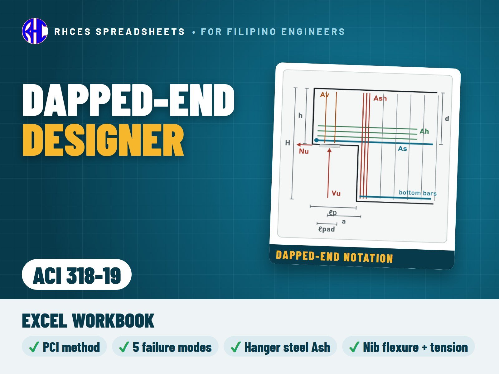
Dapped-End Designer (ACI 318-19)
Design the dapped end of a precast or reinforced-concrete beam by the PCI Design Handbook method (Mattock & Chan 1979; PCI Design Handbook 7th / 8th ed.; Klein, Botros, Andrews & Holloway, PCI Journal 2017) in SI units, with every code part (phi factors, shear friction, bearing, development length, cover, bar spacing, minimum steel, shear) taken from ACI 318-19 (SI units).
The five PCI failure modes are designed and checked: flexure with axial tension in the extended end (nib); direct shear at the dap face by shear friction; diagonal tension at the re-entrant corner (hanger steel Ash); diagonal tension in the extended end (Av and Ah); diagonal tension in the undapped end with the anchorage of As and of the main bottom bars. Plus bearing, the minimum Nu, geometry limits, spacing and cover. A live elevation of the dapped end shows the nib, the re-entrant corner, the bearing and every bar group. Strut-and-tie is out of scope.
Every result is a visible Excel formula with ACI 318-19 section references. Includes the Excel workbook. A worked A4 sample calculation can be previewed with View sample on the store page. One licence per engineer or office. Looking for the Philippine code? See the NSCP 2015 edition.
Excel · A4 calc sheet + live dapped-end elevation · SI units
Prestressed
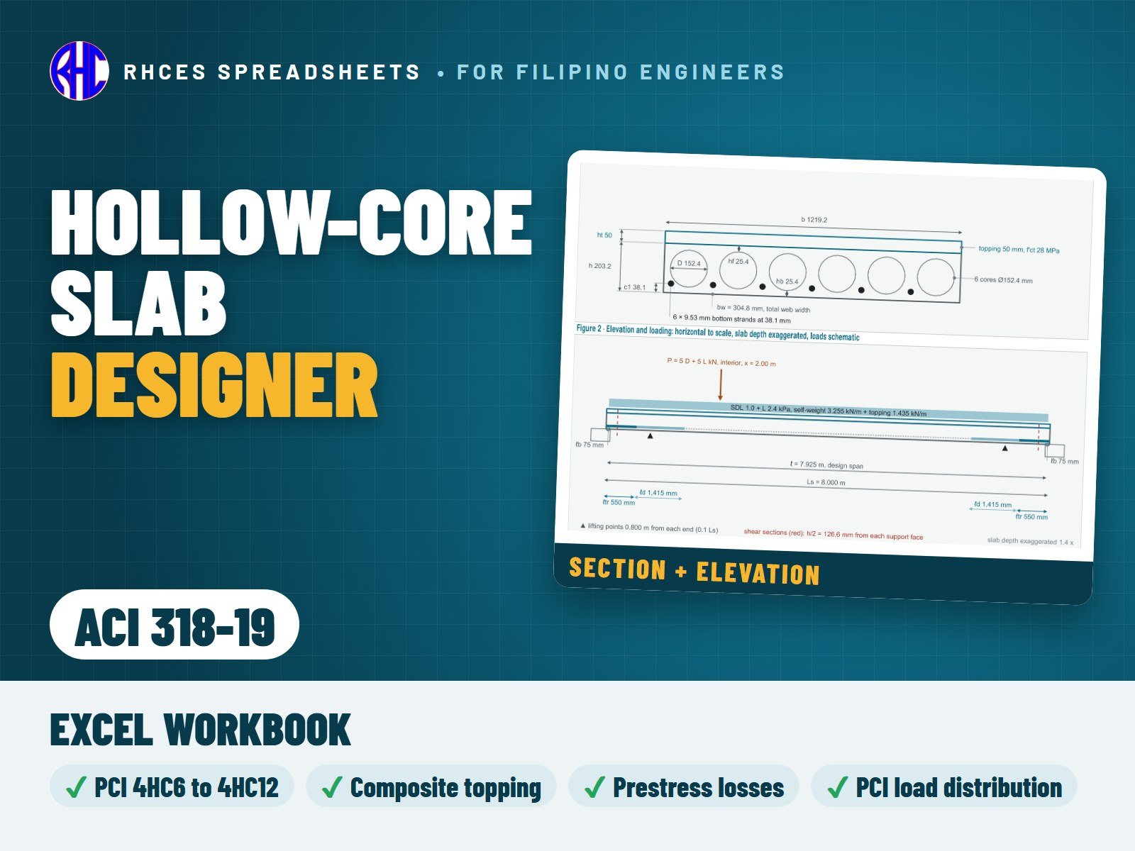
Hollow-Core Slab Designer (ACI 318-19)
Design one precast, pretensioned hollow-core slab unit, simply supported, with straight bonded strands, untopped or with an unshored composite topping, by ACI 318-19 (SI units) and the PCI methods. Pick a PCI generic section (4HC6, 4HC8, 4HC10 or 4HC12) from the library, type a circular-core section, or enter your producer's section data. One layer of bottom strands and optional top strands, normalweight concrete, uniform loads, a transverse line load (a wall across the span), a concentrated load and a longitudinal line load (a wall along the span) with the PCI load distribution.
Checks: prestress losses by the PCI method; stresses at transfer, at service and in handling; flexural strength by strain compatibility or the ACI approximate equation, with the compression block through the topping, the top flange and the cores; strand development and the design strength along the span; shear strength Vci and Vcw at 45 stations with the prestress reduced in the transfer zone (dry-cast units carry no stirrups) and the hollow-core shear rule; horizontal shear of the topping; camber, long-term position and deflections; bearing and cover.
Two live figures redraw from your inputs: the cross-section with its dimensions, strands and cores, and the elevation with the loads, bearings, transfer and development zones, lifting points and shear sections. The Design Check Summary lists every check with its ratio and status and ends in one overall result: HOLLOW-CORE SLAB ADEQUATE, ADEQUATE · SEE CHECKS, REVISE THE SLAB or INCOMPLETE DATA. Not covered: continuous or cantilevered slabs, debonded strands, mild bars in the cores, filled cores, openings and notches, diaphragm action, fire rating, lightweight concrete, vibration, ASD, Class C (cracked) design and load tables. The PCI generic sections are for preliminary design: use your producer's section and strand positions for the final design. The Read Me lists the items worth confirming.
References: ACI 318-19 in SI (ACI 318M-19) for strength, serviceability and detailing; PCI MNL-126-98 (2nd ed.) for losses, camber, composite design and load distribution; PCI Design Handbook 7th edition for the generic sections and the handling multipliers, with the printed page of each reference shown in the workbook. NSCP 2015 is not included in this edition. The method was checked against the worked examples of PCI MNL-126-98 (losses, stresses, flexural and shear strength, camber and deflection).
Every result is a visible Excel formula with ACI 318-19 section references. Includes the Excel workbook. View sample on the store page previews a worked A4 sample calculation (an office floor slab, 4HC8 with a 50 mm topping, six 9.53 mm strands, slab length 8.0 m). One licence per engineer or office.
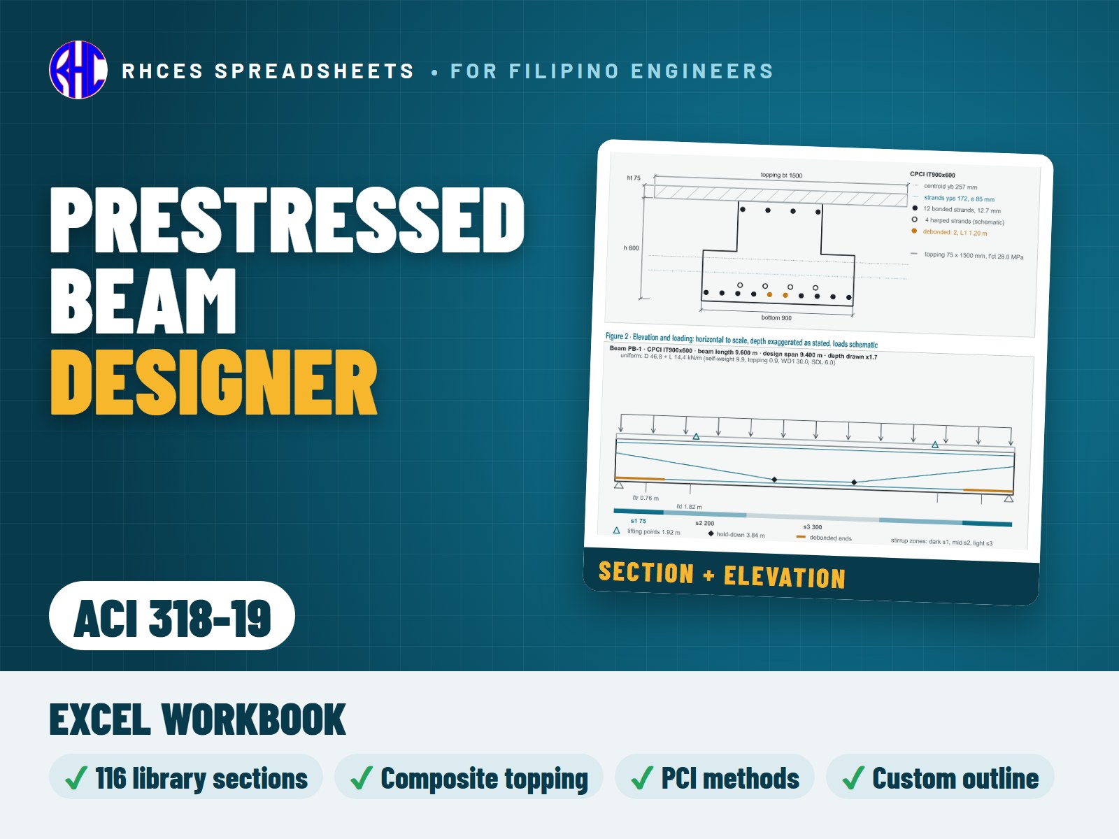
Design one precast, pretensioned, simply supported concrete beam by ACI 318-19 (SI) and the PCI methods, with or without an unshored composite topping. Pick the section from the library (116 sections: rectangular beams, L-beams, inverted tees and double tees of the PCI Design Handbook 7th ed., CPCI inverted tees and I-girders, AASHTO Types I to VI and PCI bulb tees) or type a custom outline (rectangular, I, T or inverted-T, L-beam, double tee or box). Every library section is computed from its dimensions and agrees with the published area and moment of inertia within 0.5 %. Generic sections are for preliminary design: use your producer's section for the final design.
Strands: Grade 1860 low-relaxation strand in up to 6 rows, each straight or harped, with debonded strands of up to two lengths; optional bottom and top mild bars; stirrups in three zones.
Checks: prestress losses by the PCI method (or your typed total loss); stresses at transfer, in handling and at service (Class U, or Class T if you accept it); flexural strength by strain compatibility along the span, with the transfer and development of every strand group; minimum strength 1.2 Mcr; shear Vci and Vcw along the span with the stirrup zones, minimum shear reinforcement, maximum spacing and the section limit; horizontal shear of the topping; end-zone (bursting) steel; bearing; cover; camber and deflections with the PCI multipliers. New in v1.1: when handling tension is above fr/1.5, the workbook shows the top steel required to carry it and checks the bars you provide. Four drawings redraw from your inputs: the section with its strands, the elevation with the strand profile, loads and stirrup zones, the stress diagrams, and the moment and shear diagrams against the design strength. The Design Check Summary collects every check under one overall result: PRESTRESSED BEAM ADEQUATE, ADEQUATE · SEE CHECKS, REVISE THE BEAM or INCOMPLETE DATA — SEE CHECKS.
Not covered: post-tensioning (use the RHCES Post-Tensioned Beam Designer), continuous or cantilevered beams, shored construction, lightweight concrete, torsion (spandrel beams), the design of ledges, hangers and dapped ends (use the RHCES Corbel and Dapped-End designers), bridge girders by AASHTO LRFD, fire rating, seismic frame design, vibration and Class C (cracked) design.
References: ACI 318M-19; PCI Design Handbook 7th ed.; PCI MNL-126-98; CPCI Design Manual; Dolan and Hamilton, Prestressed Concrete (2019), with the printed page of each reference shown in the workbook.
The method was checked against 133 published values from the worked examples of the PCI Design Handbook, MNL-126 and Dolan and Hamilton (losses, stresses, flexure, debonded strands, end zone, shear, horizontal shear, camber and deflection), and every number was compared with a second, independent calculation.
Every result is a visible Excel formula. Includes the Excel workbook. View sample on the store page previews a worked A4 sample calculation (13 pages: office floor beam, CPCI IT900x600 inverted tee, 9.6 m long, 75 mm composite topping, 18 strands of 12.7 mm (straight, harped and debonded); result PRESTRESSED BEAM ADEQUATE, governed by the service tension at the bottom, ratio 0.91). The sample is illustrative. One licence per engineer or office.
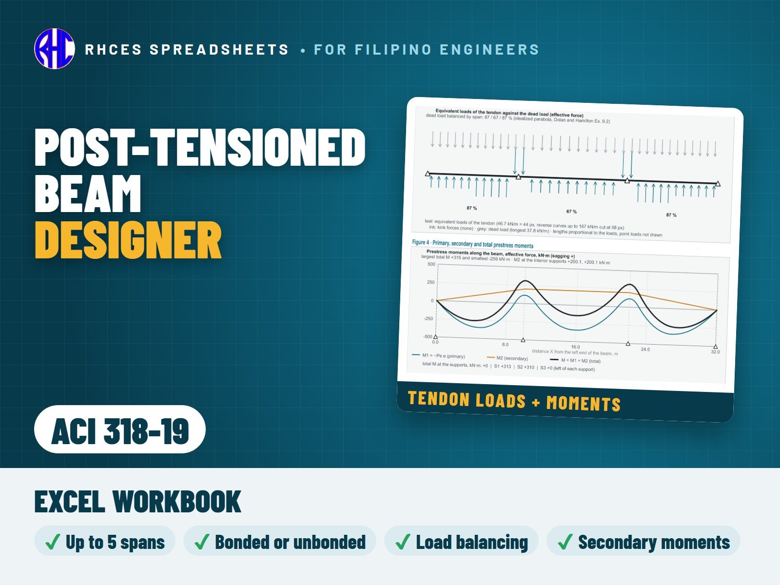
Design one cast-in-place post-tensioned concrete beam by ACI 318-19 (SI) with the loss, load-balancing and secondary-moment methods of Dolan and Hamilton: a rectangular, T or L section, a simple span or two to five continuous spans, bonded or unbonded tendons, a parabolic or harped profile in each span. The workbook follows the tendon along the whole beam (275 stations) and names the governing check.
Checks: friction and anchor-set losses, elastic shortening, creep, shrinkage and relaxation (or your typed long-term loss); equivalent loads of the tendon and the share of the dead load balanced; primary and secondary prestress moments of the continuous beam; stresses at transfer and at service (Class U, or Class T by your option), with the bonded steel for transfer tension; flexural strength with fps for bonded and unbonded tendons; minimum strength 1.2 Mcr and As,min (0.004 Act for unbonded); shear Vci and Vcw with Vp and the stirrup zones; deflection (transfer camber, sustained, live and long-term); the anchorage zone (bursting, end-zone ties, spalling steel); cover. All 36 checks are listed in the Design Check Summary with demand, capacity, ratio and status under one overall result: PT BEAM ADEQUATE, ADEQUATE · SEE CHECKS, REVISE THE BEAM or INCOMPLETE DATA — SEE CHECKS. Eight live drawings redraw from your inputs.
Not covered: two-way and one-way slabs, cantilevers, frame action with columns, several tendon groups, lightweight concrete, torsion, the local zone of the anchorage (your tendon supplier designs it), bridges (AASHTO), fire and seismic design.
References: ACI 318M-19; Dolan and Hamilton, Prestressed Concrete: Building, Design, and Construction (Springer 2019), with the printed page of each reference shown in the workbook.
The method was checked against 112 published values and hand checks, 101 of them from the worked examples of Dolan and Hamilton (Examples 4.1 to 4.8, 5.7 and 9.1 to 9.7): 104 agree within 1 % (2 % where the example reads a figure) and 8 differ because the printed example differs from its own arithmetic, as explained in the workbook. Every named result was also compared with a second, independent calculation.
Every result is a visible Excel formula. Includes the Excel workbook. View sample on the store page previews a worked A4 sample calculation (18 pages: office floor beam of three continuous spans 10.0 + 12.0 + 10.0 m, bonded T-beam with a 400 x 750 mm web and a 150 mm slab, two tendons of four 12.7 mm strands; result ADEQUATE · SEE CHECKS, governed by the transfer tension, ratio 0.93, with the anchorage zone flagged for confirmation by the tendon supplier). The sample is illustrative. One licence per engineer or office.
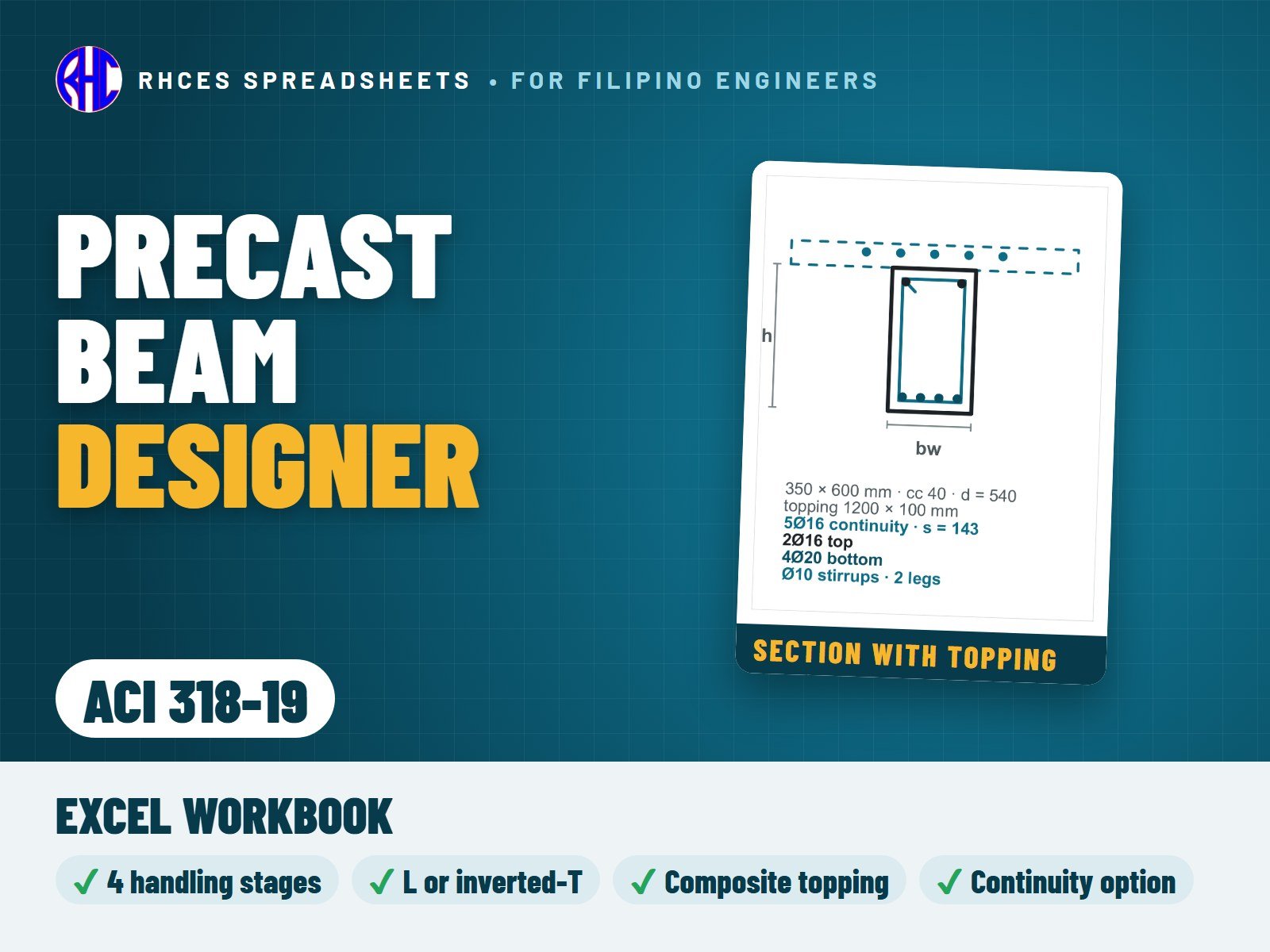
Design one reinforced (non-prestressed) precast concrete beam through its whole life by ACI 318-19 (SI): a rectangular, L-beam (one ledge) or inverted-T (two ledges) section, an optional cast-in-place topping, a simple span or continuity at one or both ends. The workbook follows the beam from the form to the finished floor in four handling stages, on its bearings, as a composite beam and at its supports, and names the governing check.
Checks: handling in four stages (stripping from the form, storage, transport and the erection lift) with the PCI equivalent static multipliers, the lift points, the sling angle, the crack-free limit fr/1.5 (a face over it is checked as a cracked section) and the insert load against your safe working load; erection of the precast beam alone, simply supported on its bearings under its own weight, the topping and the construction load, in flexure, shear and bar spacing; the final composite beam in flexure and shear, and the horizontal shear at the interface (16.4, with the interface ties); continuity, with the negative moment over the support by Table 6.5.2 from the loads placed after the topping hardens, the continuity bars in the topping, their spacing and development; the bearing: bearing length, pad set-back and bearing strength, the elastomeric pad (stress, thickness, rotation), the beam-end bearing steel (shear friction and the restraint force), and the grouted dowel in its grout tube (shear friction, embedment in the tube, development in the support, space in the tube, concrete round the tube, cover to the support face, grout strength, ties); cover, bar spacing, crack control and the deflections. All 53 checks are listed in the Design Check Summary with demand, capacity, ratio and status under one overall result: PRECAST BEAM ADEQUATE, ADEQUATE · SEE CHECKS, REVISE or CHECK INPUTS.
Four live drawings redraw from your inputs: the section with the ledges, the topping, the stirrups and the bars at true scale; the handling moment diagram of the governing stage against the crack-free limits; the factored moments of the erection and final stages against the design strengths; and the longitudinal section of the beam with its bars, stirrups, supports, pads, dowels and tubes. The sheet lists the factored reaction Vu, the horizontal restraint Nuc and the pad size to type into the RHCES Corbel Designer (column corbel) or the RHCES Dapped-End Designer (dapped end), both on this store.
Not covered: prestressed and post-tensioned beams (see the RHCES Prestressed and Post-Tensioned Beam Designers), the capacity of lifting inserts and the concrete breakout round them (the insert supplier), rigging and roll stability, ledge hangers and punching of the ledge, pad slip, proprietary grouted splice sleeves, torsion, seismic precast frames, lightweight concrete, fire rating. The pad, the design movement at the beam end and the tube and grout data are yours to supply; the Read Me lists them.
References: ACI 318-19 (SI); PCI Design Handbook, 7th edition; the strength, shear and bar-spacing checks are those of the RHCES RC Beam Section Designer v1.1 for the same code, with the printed page and the PDF page of each reference shown in the workbook.
The workbook was compared with an independent calculation of the sample, of the edge cases of every rule and of 300 random designs; its section checks agree with the RC Beam Section Designer v1.1 for the same inputs, and the pad, beam-end and dowel checks were also recomputed by hand.
Every result is a visible Excel formula. Includes the Excel workbook. View sample on the store page previews a worked A4 sample calculation (16 pages: Beam PB-1, rectangular 350 x 600 mm, 7.50 m between bearing centres, f'c 28 MPa (f'ci 20 MPa at stripping), 4Ø20 bottom bars and 2Ø16 top bars, a 100 mm topping with 5Ø16 continuity bars at one end, a 250 mm bearing with a 15 mm pad, and one Ø16 dowel in a Ø50 tube at each end; result PRECAST BEAM ADEQUATE, governed by the deflection after attachment, ratio 0.87). The sample is illustrative. One licence per engineer or office.