
RHCES Spreadsheets

Spreadsheets that do the work.

Buy in one click, pay by GCash, Maya, QR Ph or PayPal, and your download appears as soon as the payment clears.

All products are non-refundable. Please check the details and price before you pay.
Licensed to the buyer only (one engineer or office). Sharing, uploading or reselling a product, or forwarding its download link, without the written permission of RHCES is prohibited. By buying you agree to our Terms of Service.

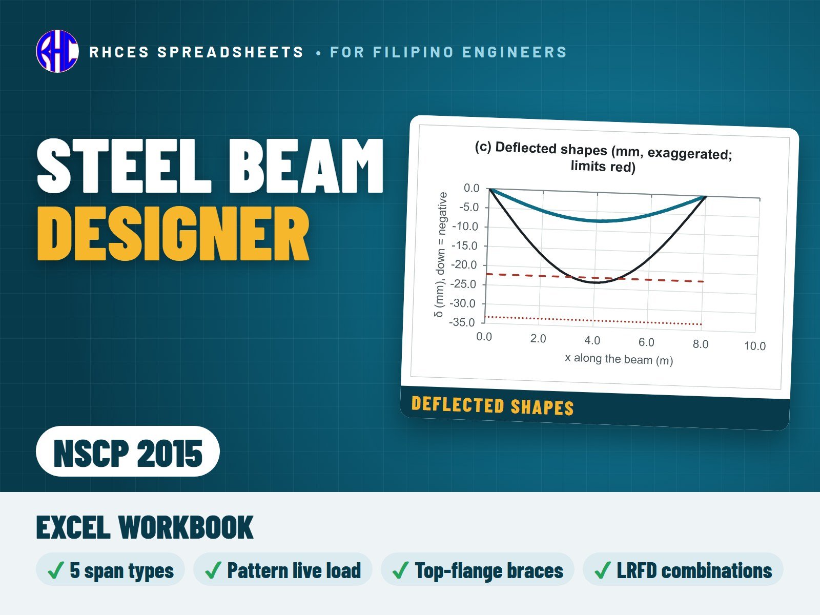
Preview of Steel Beam Designer (NSCP 2015)
Steel

Steel Beam Designer (NSCP 2015)

Design one steel beam at a time to NSCP 2015 Chapter 5 in LRFD. Pick a W shape, JIS H-section, C or MC channel or rectangular or square HSS from the libraries in the workbook, or type a Custom I-section (rolled or welded) or Custom HSS. The span is simple, a cantilever, a propped cantilever, fixed at both ends or two continuous spans, with the top-flange brace points you set. Type the service loads by case (area loads on a tributary width plus up to 12 uniform, partial-uniform or point loads on the major or minor axis); they are combined by the NSCP 203.3.1 LRFD combinations, with pattern live load on two spans. Or type the design forces from your own analysis.

Checks: section classification; major-axis flexure (yielding, lateral-torsional buckling by unbraced segment with Cb from the moment diagram, flange and web local buckling); minor-axis flexure and biaxial interaction; shear about both axes; optional holes in the tension flange; flange local bending, web local yielding, web crippling, web sidesway buckling and web compression buckling under the support reactions and flange-applied point loads, with the need for bearing stiffeners and an optional stiffener-pair design; the unframed bearing end of NSCP 510.10.7 (every bearing support reads CHECK until a stiffener pair is provided; you decide whether the end is restrained instead); and deflection under variable and total service loads.

Live drawings show the section, the span with its supports, braces and loads, and the moment, shear and deflection diagrams. The Design Check Summary reports PASS / FAIL / CHECK / N/A for every check and ends in one overall result: STEEL BEAM ADEQUATE, ADEQUATE · SEE CHECKS, REVISE THE BEAM or INCOMPLETE DATA. Not covered: axial force and beam-columns, torsion, round HSS and pipe, tees and angles, noncompact or slender I-section webs, shear stiffeners, web openings, coped ends, composite and cold-formed members, connection and bracing design, more than two spans, moving loads, ponding, vibration, fatigue, fire, the special seismic combinations, live-load reduction and ASD. The Read Me lists the items worth confirming.

References: NSCP 2015 (7th ed.) Chapter 2 (203.3.1 load combinations) and Chapter 5 (Tables 502.4.1 and 502.4.2 classification, 503.1, 506.1 to 506.3, 506.6 and 506.7 flexure and Cb, 506.13 holes, 507 shear, 508.1.1 biaxial bending, 510.10 concentrated forces and stiffeners), with the printed page of each reference shown in the workbook. Not in NSCP 2015 and labelled so in the workbook: the deflection limits and the wind fraction (IBC Table 1604.3), the HSS lateral-torsional buckling check and the JIS steel grades. The section data come from the AISC Shapes Database and the Nippon Steel Shapes list (JIS G 3192).

Every result is a visible Excel formula, with printed NSCP 2015 clause and page references for the code items. Includes the Excel workbook. View sample on the store page previews a worked A4 sample calculation (a girder of a two-storey commercial building). One licence per engineer or office.
Excel · A4 calc sheets + live section, span, moment, shear and deflection drawings; View sample: 9 pages
₱449.00View sample
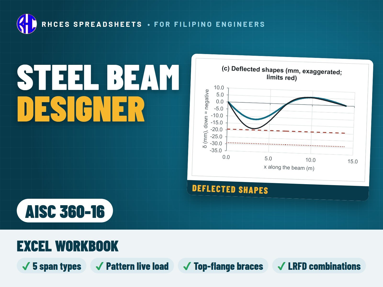
Preview of Steel Beam Designer (AISC 360-16)
Steel

Steel Beam Designer (AISC 360-16)

Design one steel beam at a time to AISC 360-16 in LRFD. Pick a W shape, JIS H-section, C or MC channel or rectangular or square HSS from the libraries in the workbook, or type a Custom I-section (rolled or welded) or Custom HSS. The span is simple, a cantilever, a propped cantilever, fixed at both ends or two continuous spans, with the top-flange brace points you set. Type the service loads by case (area loads on a tributary width plus up to 12 uniform, partial-uniform or point loads on the major or minor axis); they are combined by the ASCE/SEI 7-22 LRFD combinations, with pattern live load on two spans. Or type the design forces from your own analysis.

Checks: section classification; major-axis flexure (yielding, lateral-torsional buckling by unbraced segment with Cb from the moment diagram, flange and web local buckling); minor-axis flexure and biaxial interaction; shear about both axes; optional holes in the tension flange; flange local bending, web local yielding, web crippling, web sidesway buckling and web compression buckling under the support reactions and flange-applied point loads, with the need for bearing stiffeners and an optional stiffener-pair design; the unframed bearing end of AISC 360-16 J10.7 (every bearing support reads CHECK until a stiffener pair is provided; you decide whether the end is restrained instead); and deflection under variable and total service loads.

Live drawings show the section, the span with its supports, braces and loads, and the moment, shear and deflection diagrams. The Design Check Summary reports PASS / FAIL / CHECK / N/A for every check and ends in one overall result: STEEL BEAM ADEQUATE, ADEQUATE · SEE CHECKS, REVISE THE BEAM or INCOMPLETE DATA. Not covered: axial force and beam-columns, torsion, round HSS and pipe, tees and angles, noncompact or slender I-section webs, shear stiffeners, web openings, coped ends, composite and cold-formed members, concentrated forces on HSS walls, connection and bracing design, more than two spans, moving loads, ponding, vibration, fatigue, fire, the special seismic combinations, live-load reduction and ASD. The Read Me lists the items worth confirming.

References: ANSI/AISC 360-16 (July 7, 2016): A3.1, B2 to B4, E3, E4, F1 to F3, F6, F7, F13, G1, G2, G4, G6, H1, J2, J4, J7, J10, L2 and Appendix 6, with the printed page of each reference shown in the workbook, and the ASCE/SEI 7-22 load combinations (2.3.1 and 2.3.6); ASCE/SEI 7-16, which AISC 360-16 lists, has other snow factors, and the Read Me says where to check them. Not part of AISC 360-16 and marked so: the deflection limits and the wind fraction (IBC Table 1604.3 practice), the JIS steel grades and the section data (AISC Shapes Database, Nippon Steel Shapes list). The workbook reproduces the published AISC Design Examples listed in its Read Me.

Every result is a visible Excel formula, with printed AISC 360-16 clause and page references. Includes the Excel workbook. View sample on the store page previews a worked A4 sample calculation (an equipment platform beam in an industrial plant: W410x46.1, two 7.0 m continuous spans on column cap plates, pattern live load). One licence per engineer or office.
Excel · A4 calc sheets + live section, span, moment, shear and deflection drawings; View sample: 9 pages
₱449.00View sample
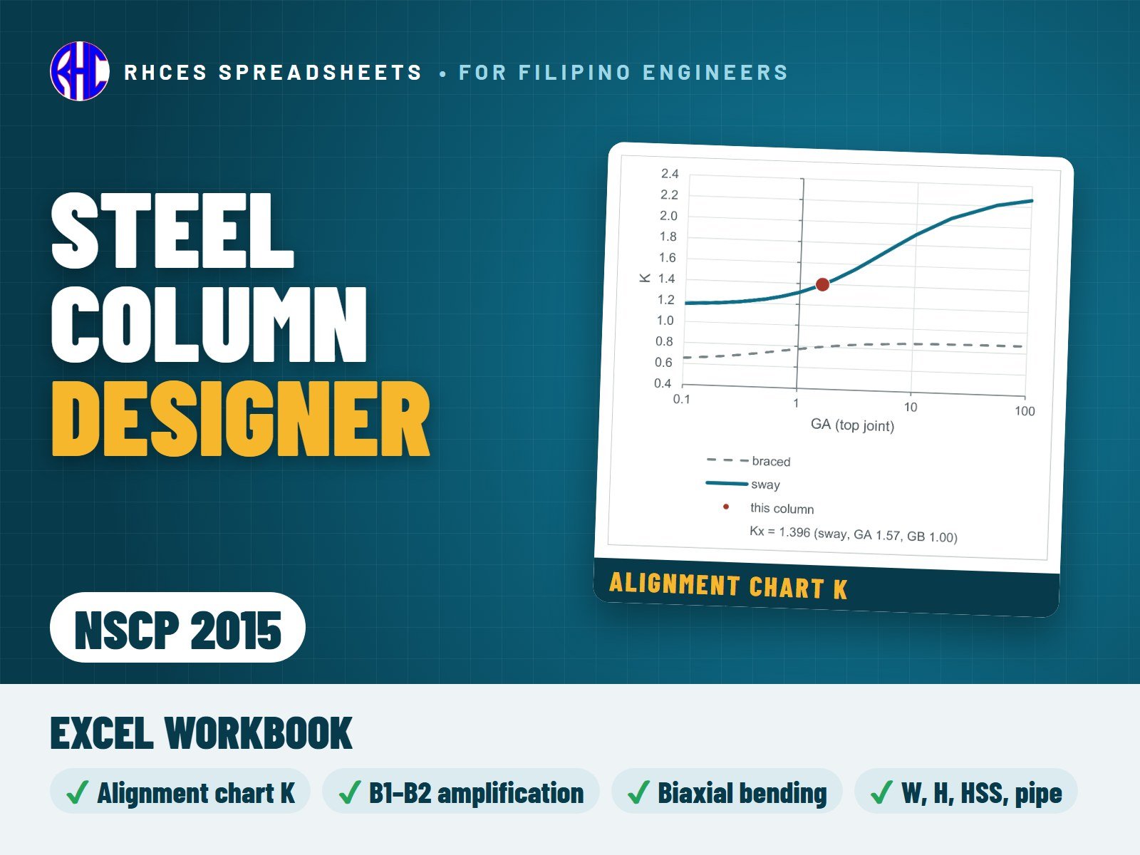
Preview of Steel Column Designer (NSCP 2015)
Steel

Steel Column Designer (NSCP 2015)

Check one steel column or beam-column to NSCP 2015 Chapter 5 in LRFD, for one set of factored forces: axial compression or axial tension combined with bending about both axes. Pick a W shape, JIS H-shape, rectangular, square or round hollow section or pipe from the libraries, or type an I-shape, rectangular tube or round tube. The effective length factor K comes from a typed value, the ideal end conditions or the alignment chart (braced or sway, with G from the connected members). The required strengths are amplified in the workbook by the B1 and B2 method of NSCP 503.2.1.2, or typed from your own second-order analysis. Choose the effective length method, the first-order method or the direct analysis method.

Checks: slenderness; flexural buckling and torsional buckling; slender elements by the Q factors; axial tension; flexure with lateral-torsional and local buckling; shear in both directions; combined axial force and bending, with the optional single-axis method; the drift-ratio limit of the stability method you choose; and the amplifier stability (B1, B2).

The Diagrams sheet draws the section, the column with its effective lengths, K against GA, the interaction diagram with the design point and the moments along the height. The Design Check Summary reports PASS / FAIL / CHECK / N/A for every check and ends in one overall result: COLUMN ADEQUATE, ADEQUATE · SEE CHECKS, REVISE THE COLUMN or INCOMPLETE DATA. Not covered: channels, angles, tees and double angles; welded built-up, box, cruciform, laced or battened columns; composite, tapered or stepped columns; I-shapes with a noncompact or slender web in flexure; HSS with a slender web in flexure; round HSS with D/t not below 0.45E/Fy; torsion; web openings; the seismic provisions of NSCP Part 2A; the frame analysis itself; leaning-column K adjustments; ASD; fire; serviceability; connections, splices, base plates and bracing design. The Read Me lists the items worth confirming.

References: NSCP 2015 (Vol. I, 7th Ed.) Chapter 5 (502.4 classification, 503.2 stability and Appendix A-7, 504 tension, 505 compression and slender elements, 506 flexure, 507 shear, 508.1 combined forces) and the 203.3.1 and 203.5 load combinations, with the printed page of each reference shown in the workbook. Not in NSCP 2015 and marked so: the alignment chart and the girder far-end corrections (AISC Commentary on Appendix 7 and the AISC LRFD Manual, 2nd Edition). The section data come from the AISC Shapes Database and the Nippon Steel Shapes list (JIS G 3192).

Every result is a visible Excel formula, with printed NSCP 2015 clause and page references for the code items. Includes the Excel workbook. View sample on the store page previews a worked A4 sample calculation (a ground-storey column of a three-storey steel office building). One licence per engineer or office.
Excel · Column Design, Diagrams and Summary (A4); live K chart and interaction diagram; View sample: 7 pages
₱449.00View sample
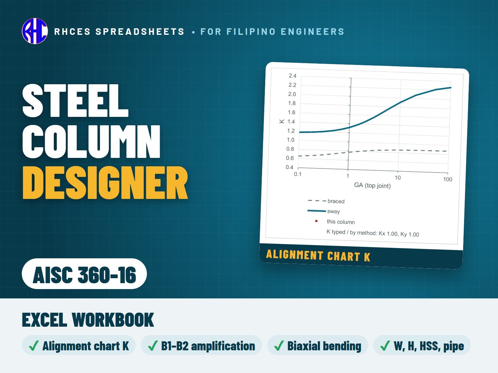
Preview of Steel Column Designer (AISC 360-16)
Steel

Steel Column Designer (AISC 360-16)

Check one steel column or beam-column to AISC 360-16 in LRFD, for one set of factored forces: axial compression or axial tension combined with bending about both axes. Pick a W shape, JIS H-shape, rectangular, square or round hollow section or pipe from the libraries, or type an I-shape, rectangular tube or round tube. The effective length factor K comes from a typed value, the ideal end conditions or the alignment chart (braced or sway, with G from the connected members). The required strengths are amplified in the workbook by the B1 and B2 method of Appendix 8, or typed from your own second-order analysis. Choose the direct analysis method (the default), the effective length method or the first-order method.

Checks: slenderness; flexural buckling and torsional buckling, with constrained-axis torsional buckling by Commentary Eq. C-E4-1 when the bracing is offset from the shear centre; slender elements by effective widths; axial tension; flexure with lateral-torsional and local buckling; shear in both directions; combined axial force and bending (H1.1 and H1.2, with the optional single-axis method H1.3); the drift-ratio limit of the stability method you choose; and the amplifier stability (B1, B2).

The Diagrams sheet draws the section, the column with its effective lengths, K against GA, the interaction diagram with the design point and the moments along the height. The Design Check Summary reports PASS / FAIL / CHECK / N/A for every check and ends in one overall result: COLUMN ADEQUATE, ADEQUATE · SEE CHECKS, REVISE THE COLUMN or INCOMPLETE DATA. Not covered: channels, angles, tees and double angles; welded built-up, box, cruciform, laced or battened columns; composite, tapered or stepped columns; I-shapes with a noncompact or slender web in flexure; HSS with a slender web in flexure; round HSS with D/t not below 0.45E/Fy; torsion; web openings; the seismic provisions (AISC 341-16); the frame analysis itself; leaning-column K adjustments; ASD; fire; serviceability; connections, splices, base plates and bracing design. The Read Me lists the items worth confirming.

References: ANSI/AISC 360-16 (July 7, 2016): Chapter C, Appendices 7 and 8, D2, D3, E3, E4, E7, F1 to F8, G2, G4 to G6 and H1, with the printed page of each reference shown in the workbook. The forces are typed from your analysis; the sample and the notes use the ASCE/SEI 7-22 combinations (2.3.1 and 2.3.6), and the Read Me notes that AISC 360-16 lists ASCE/SEI 7-16, so use the combinations of the code edition your project follows. Not part of the Specification and marked so: the alignment chart and the constrained-axis torsional buckling stress (AISC Commentary), and the section data (AISC Shapes Database, Nippon Steel Shapes list).

Every result is a visible Excel formula, with printed AISC 360-16 clause and page references. Includes the Excel workbook. View sample on the store page previews a worked A4 sample calculation (a W360x101 column of a pipe rack bent, 6.0 m, direct analysis method: B2 = 1.13, design compressive strength 2,040 kN, interaction ratio 0.96). One licence per engineer or office.
Excel · Column Design, Diagrams and Summary (A4); live K chart and interaction diagram; View sample: 7 pages
₱449.00View sample
Preview of Steel Base Plate & Anchor Bolt Designer (NSCP 2015)
Steel

Steel Base Plate & Anchor Bolt Designer (NSCP 2015)

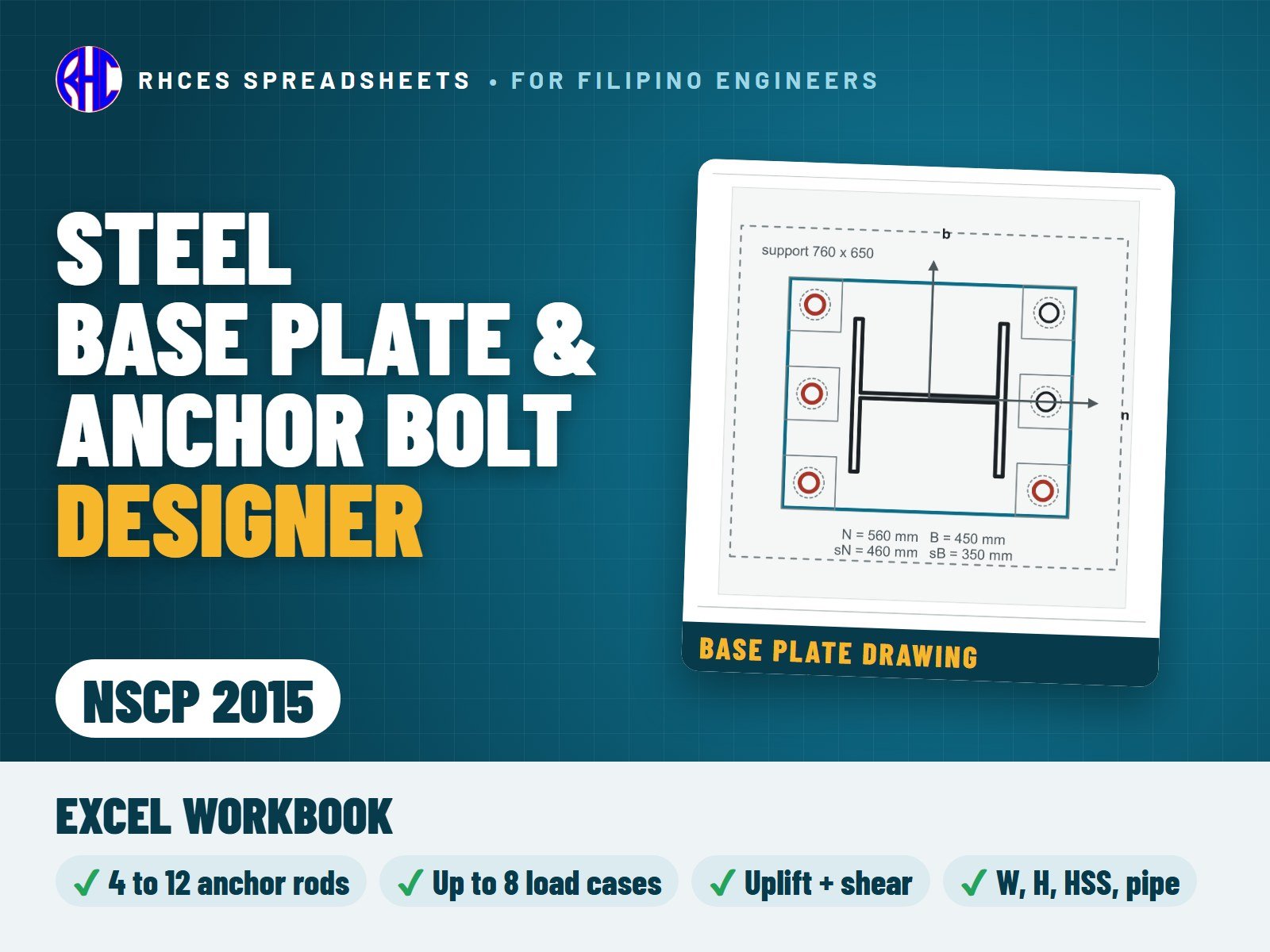
Check one exposed steel column base at a time to NSCP 2015 in LRFD. The column is a W shape, JIS H-section, rectangular, square or round HSS or pipe from the libraries, or a typed I-section, rectangular tube or round tube, centred on a rectangular base plate with a grout bed on a concrete pedestal or footing (the plate may be offset on the support). The base has 4 to 12 cast-in anchor rods in a symmetric rectangular pattern, headed with a heavy hex nut, headed with a plate washer, or hooked. Enter up to eight factored load cases: axial compression or uplift, moments about both axes and shear in two directions.

Checks, for every load case: concrete bearing; plate thickness at the bearing and tension interfaces; anchor rods in steel and in concrete (NSCP Section 417: steel strength, breakout in tension and shear, pullout, side-face blowout, pryout, interaction, spacing and edge distances, seismic provisions); shear transfer by the rods, by friction or by a shear lug; the column-to-plate fillet welds; and the detailing of holes, washers, spacing and edge distances. The bearing and anchor forces come from the uniform-bearing method of AISC Design Guide 1.

Live drawings show the plan, the elevation, the bearing and anchor-tension diagrams and the moment-axial strength curves of the base. The Design Check Summary is the envelope over the load cases and ends in one overall result: BASE CONNECTION ADEQUATE, ADEQUATE · SEE CHECKS, REVISE THE BASE CONNECTION or INCOMPLETE DATA. Not covered: embedded column bases, stiffened or built-up base plates, post-installed, adhesive or screw anchors, non-rectangular or staggered rod patterns, rods of different sizes, footing and pedestal design, several shear lugs in one direction, stiffened lugs, yield-line plate analysis, fatigue, ASD and fire. The Read Me lists the items worth confirming.

References: NSCP 2015 (Vol. I, 7th Edition) Chapter 5 (510.2 welds, 510.3 threaded parts, combined forces and bearing at holes, 510.4 connecting elements, 510.8 bearing on concrete, 510.9 anchor rods), Section 417 (anchoring to concrete), 422.8 and 422.9 (bearing and the friction limit) and the 203.3.1 and 203.5 load combinations, with the printed page of each reference shown in the workbook. Not in NSCP 2015 and marked so: the column-base method (AISC Design Guide 1, 3rd edition, 2024) and shear lugs (ACI 318M-19 17.11).

Every result is a visible Excel formula, with printed NSCP 2015 clause and page references for the code items. Includes the Excel workbook. View sample on the store page previews a worked A4 sample calculation (a moment-frame column base with six M36 anchor rods and four load cases). One licence per engineer or office.
Excel · Base Plate, Plate & Bearing, Anchors, Drawings and Summary sheets (A4); View sample: 14 pages
₱449.00View sample
Preview of Steel Base Plate & Anchor Bolt Designer (AISC 360-16)
Steel

Steel Base Plate & Anchor Bolt Designer (AISC 360-16)

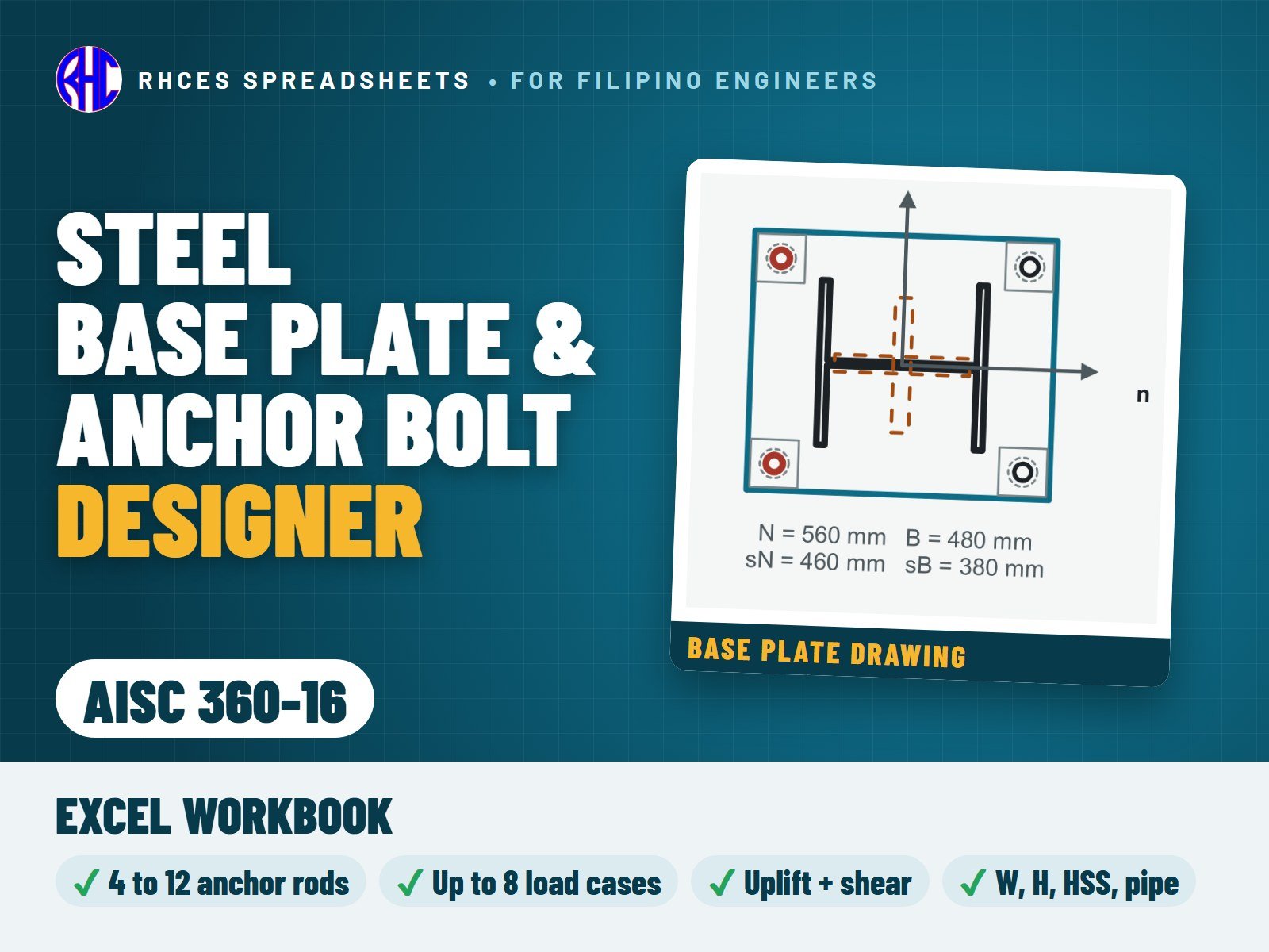
Check one exposed steel column base at a time to AISC 360-16 and ACI 318M-19 in LRFD. The column is a W shape, JIS H-section, rectangular, square or round HSS or pipe from the libraries, or a typed I-section, rectangular tube or round tube, centred on a rectangular base plate with a grout bed on a concrete pedestal or footing (the plate may be offset on the support). The base has 4 to 12 cast-in anchor rods in a symmetric rectangular pattern, headed with a heavy hex nut, headed with a plate washer, or hooked. Enter up to eight factored load cases: axial compression or uplift, moments about both axes and shear in two directions.

Checks, for every load case: concrete bearing; plate thickness at the bearing and tension interfaces; anchor rods in steel and in concrete (ACI 318M-19 Chapter 17: tension 17.6, shear 17.7, interaction 17.8, spacing and edge distances 17.9 and the seismic provisions 17.10); shear transfer by the rods, by friction or by a shear lug (ACI 318M-19 17.11); the column-to-plate fillet welds; and the detailing. The bearing and anchor forces come from the uniform-bearing method of AISC Design Guide 1.

Live drawings show the plan, the elevation, the bearing and anchor-tension diagrams and the moment-axial strength curves of the base. The Design Check Summary is the envelope over the load cases and ends in one overall result: BASE CONNECTION ADEQUATE, ADEQUATE · SEE CHECKS, REVISE THE BASE CONNECTION or INCOMPLETE DATA. Not covered: embedded column bases, stiffened or built-up base plates, columns not centred on the plate, post-installed, adhesive or screw anchors, non-rectangular or staggered rod patterns, rods of different sizes, footing and pedestal design, several shear lugs in one direction, stiffened lugs, yield-line plate analysis, fatigue, ASD and fire. The Read Me lists the items worth confirming.

References: ANSI/AISC 360-16 (J8 bearing on concrete, J9 anchor rods, J3 bolts and threaded parts, J2 welds, J4 connecting elements), ACI 318M-19 Chapter 17 with 22.8 and 22.9 (bearing and friction) and the ASCE/SEI 7-22 load combinations (2.3.1 and 2.3.6), with the printed page of each AISC reference shown in the workbook; the Read Me notes that AISC 360-16 lists ASCE/SEI 7-16. Not in AISC 360-16 and marked so: the column-base method (AISC Design Guide 1, 3rd edition, 2024), the shear-lug flexural-rupture formula and AISC Manual Eq. 9-1.

Every result is a visible Excel formula, with AISC 360-16 and ACI 318M-19 clause references. Includes the Excel workbook. View sample on the store page previews a worked A4 sample calculation (a pipe rack column base: W310x97 on a 560 x 480 x 45 mm plate and a 1200 x 1200 mm pedestal, four 1-1/4 in. F1554 Grade 55 rods, a cruciform shear lug, five load cases including uplift). One licence per engineer or office.
Excel · Base Plate, Plate & Bearing, Anchors, Drawings and Summary sheets (A4); View sample: 14 pages
₱449.00View sample
Preview of Steel Double-Angle Connection Designer (NSCP 2015)
Steel

Steel Double-Angle Connection Designer (NSCP 2015)

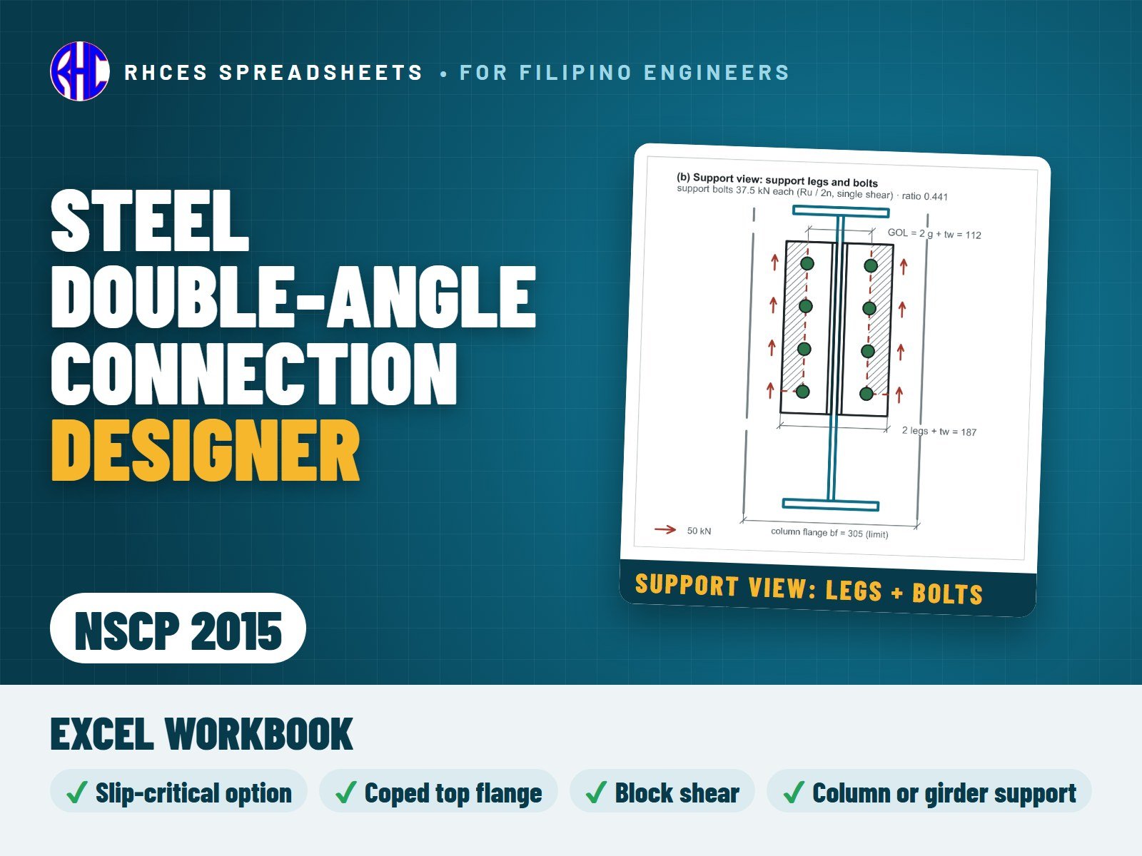
Check an all-bolted double-angle beam end connection to NSCP 2015 Chapter 5 for a factored (LRFD) end reaction: two angles with one bolt line through the beam web (double shear) and one line in each support leg (single shear), on a column flange, a column web or a girder web, with an optional coped top flange. Pick the beam, the support member and the steel grades from the libraries (W shapes, JIS H-sections, angles) or type custom ones.

Checks: detailing and fit, including the angle gages; both bolt groups (shear, bearing and tear-out, and slip resistance of slip-critical joints); angle yielding, rupture and block shear; beam web yielding, rupture and block shear; and the flexure of the coped section. The connection is drawn to scale in elevation and plan from your inputs. The Design Check Summary collects every check under one overall result: DOUBLE-ANGLE CONNECTION ADEQUATE, ADEQUATE · SEE CHECKS, REVISE THE CONNECTION or INCOMPLETE DATA. LRFD only. Not covered: seismic connection requirements, the local checks of the supporting members (column web and flange, girder web), double and long copes, the beam's own shear and flexure away from the connection, and ASD. The Read Me lists the items worth confirming.

References: NSCP 2015 (7th ed.) Chapter 5 (510.3 bolts: Tables 510.3.1 to 510.3.3 and slip-critical joints 510.3.8; 510.4 connecting elements) and the 203.3.1 load combinations, with the printed page of each reference shown in the workbook. Not in NSCP 2015 and marked so: the double-angle practice and coped beams (AISC LRFD Manual, 2nd Edition) and the section data (AISC Shapes Database, Nippon Steel Shapes list).

Every result is a visible Excel formula, with printed NSCP 2015 clause and page references for the code items. Includes the Excel workbook. View sample on the store page previews a worked A4 sample calculation (a W530x74 beam connected to a W310x97 column flange by two L89x89x7.9 angles, 300 kN). One licence per engineer or office.
Excel · Double Angle sheet with to-scale drawing and Design Check Summary (A4); View sample: 4 pages
₱399.00View sample
Preview of Steel Bolt Group Designer (NSCP 2015)
Steel

Steel Bolt Group Designer (NSCP 2015)

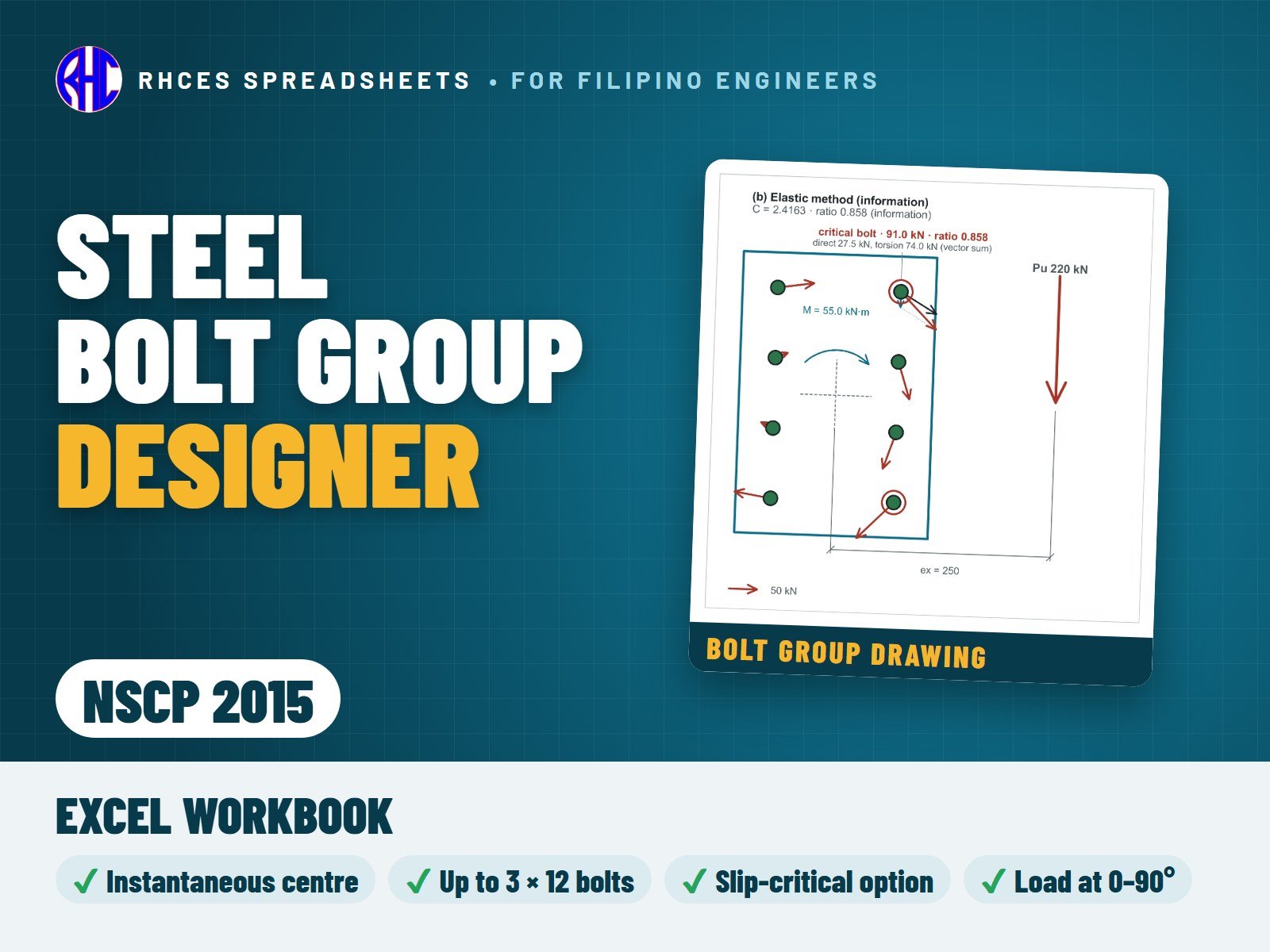
Check an eccentric bolt group loaded in its plane (brackets, lap splices) to NSCP 2015 Chapter 5 in LRFD: a rectangular pattern of up to 3 lines of 12 bolts, one or two shear planes, fillers, standard or oversized holes, snug-tight, pretensioned or slip-critical bolts, and a factored eccentric load inclined 0 to 90 degrees. Pick the thickness and grade of each ply from the Materials list, or type a custom grade.

Checks: the group by the instantaneous-centre method, with the elastic method for comparison or to govern; bolt shear, bearing and tear-out of both plies; slip resistance of slip-critical joints; and the detailing. The sheet draws the bolt pattern, the load and the instantaneous centre to scale. The Design Check Summary collects every check under one overall result: BOLT GROUP ADEQUATE, ADEQUATE · SEE CHECKS, REVISE THE BOLT GROUP or INCOMPLETE DATA. LRFD only. Not covered: the bracket plate and the supporting member away from the group, and seismic connection requirements. The Read Me lists the items worth confirming.

References: NSCP 2015 (7th ed.) Chapter 5 (510.3 bolts: Tables 510.3.1 to 510.3.3 and slip-critical joints 510.3.8) and the 203.3.1 load combinations, with the printed page of each reference shown in the workbook. Not in NSCP 2015 and marked so: the instantaneous-centre and elastic methods for eccentric bolt groups (AISC LRFD Manual, 2nd Edition, pp. 8-28 to 8-36).

Every result is a visible Excel formula, with printed NSCP 2015 clause and page references for the code items. Includes the Excel workbook. View sample on the store page previews a worked A4 sample calculation (a hoist-beam bracket: PL16 plate on a W310x97 column flange, 2 x 4 M22 bolts, 220 kN at 250 mm eccentricity). One licence per engineer or office.
Excel · Bolt Group sheet with to-scale drawing and Design Check Summary (A4); View sample: 3 pages
₱349.00View sample
Preview of Steel Weld Group Designer (NSCP 2015)
Steel

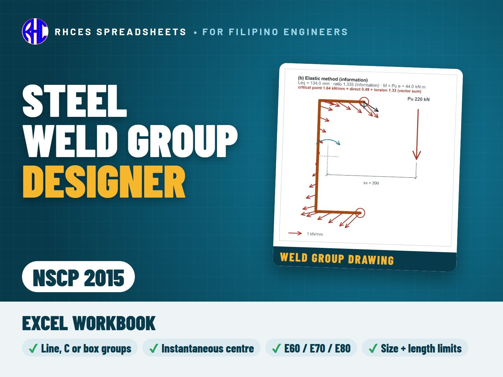
Steel Weld Group Designer (NSCP 2015)

Check an eccentric fillet-weld group loaded in its plane to NSCP 2015 Chapter 5 in LRFD: a single line, two vertical lines, two horizontal lines, a C-shape with the legs toward or away from the load, or a box. A vertical or concentric load uses the instantaneous-centre method, with the elastic method shown for comparison; an inclined eccentric load uses the elastic method. Pick the parts and the electrode (E60XX, E70XX or E80XX) from the Materials lists, or type a custom grade or electrode.

Checks: the weld group with the directional strength increase, the base metal, and the weld size and length limits. The sheet draws the weld group with the line of action and the instantaneous centre to scale. The Design Check Summary collects every check under one overall result: WELD GROUP ADEQUATE, ADEQUATE · SEE CHECKS, REVISE THE WELD GROUP or INCOMPLETE DATA. LRFD only. Not covered: the bracket plate and the supporting member away from the group, and seismic connection requirements. The Read Me lists the items worth confirming.

References: NSCP 2015 (7th ed.) Chapter 5 (510.2 welds including 510.2.4 and Table 510.2.5, 510.4.2 connecting elements) and the 203.3.1 load combinations, with the printed page of each reference shown in the workbook. The printed weld equations 510.2-6 to 510.2-8 (p. 5-94) have typing errors; the workbook uses the corrected form and says so. Not in NSCP 2015 and marked so: the instantaneous-centre procedure and the elastic method of the eccentric weld group (AISC LRFD Manual, 2nd Edition, pp. 8-154 to 8-161).

Every result is a visible Excel formula, with printed NSCP 2015 clause and page references for the code items. Includes the Excel workbook. View sample on the store page previews a worked A4 sample calculation (a canopy bracket: PL12 plate with C-shaped 8 mm fillet welds, 220 kN at 200 mm eccentricity). One licence per engineer or office.
Excel · Weld Group sheet with to-scale drawing and Design Check Summary (A4); View sample: 3 pages
₱349.00View sample
Preview of Steel Gusset Plate Designer (NSCP 2015)
Steel

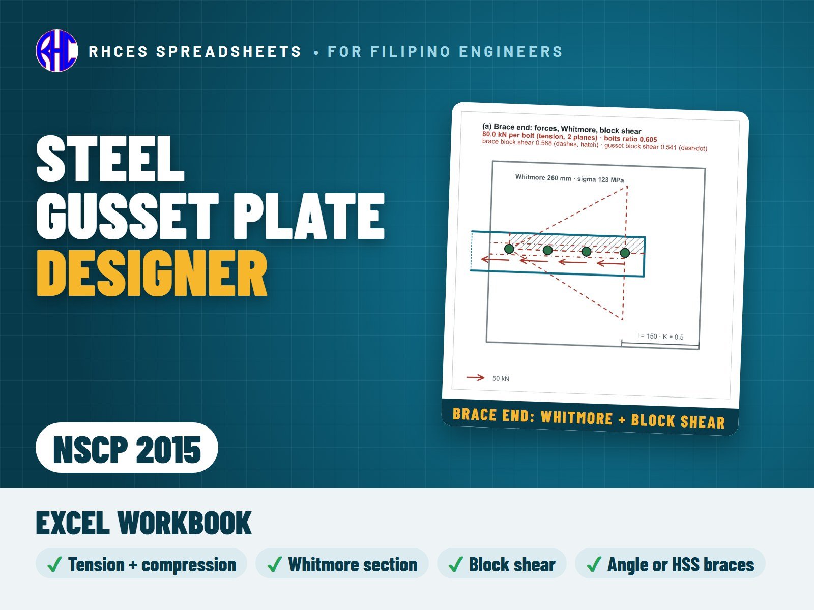
Steel Gusset Plate Designer (NSCP 2015)

Check a brace end on a gusset plate, in tension and in compression, to NSCP 2015 Chapter 5 in LRFD: bolted double-angle or single-angle braces, and rectangular HSS, round HSS or pipe braces slotted and welded to the gusset, with an optional check of the gusset-to-support weld. Pick the brace, the grades, the bolts and the electrodes from the libraries, or type a custom grade.

Checks: the bolts or welds; the brace (gross yielding, net-section rupture with shear lag, block shear or the HSS wall); the gusset (block shear, Whitmore yielding and rupture, and buckling with the length and K you type); and the optional gusset interface weld. The sheet draws the brace, the gusset and the Whitmore section to scale. The Design Check Summary collects every check under one overall result: BRACE CONNECTION ADEQUATE, ADEQUATE · SEE CHECKS, REVISE THE BRACE CONNECTION or INCOMPLETE DATA. LRFD only. Not covered: seismic connection requirements (the expected brace strength, for example), and the beam and the column at the gusset. The gusset buckling length and K, the free-edge stability and the interface forces are the engineer's responsibility. NSCP 510.4.1 prints φ = 0.75 for tensile yielding of connecting elements; the workbook uses φ = 0.90 (Section 504 and Ω = 1.67 agree with it) and the Read Me says so. The Read Me lists the other items worth confirming.

References: NSCP 2015 (7th ed.) Chapter 5 (504.3 shear lag, 505.3 compression, 510.2 welds, 510.3 bolts, 510.4 connecting elements) and the 203.3.1 load combinations, with the printed page of each reference shown in the workbook. Not in NSCP 2015 and marked so: the Whitmore section, the buckling length and K of the gusset and the interface weld (AISC LRFD Manual, 2nd Edition, Part 11; the interface-weld average follows the AISC Seismic Design Manual 2024, Ex. 5.2.4) and the section data.

Every result is a visible Excel formula, with printed NSCP 2015 clause and page references for the code items. Includes the Excel workbook. View sample on the store page previews a worked A4 sample calculation (an X-brace of two L76x76x7.9 angles on a PL10 gusset with 4 M20 bolts, 320 kN in tension and compression). One licence per engineer or office.
Excel · Gusset Plate sheet with to-scale drawing and Design Check Summary (A4); View sample: 4 pages
₱449.00View sample
Preview of Steel Connection Designer (AISC 360-16)
Steel

Steel Connection Designer (AISC 360-16)

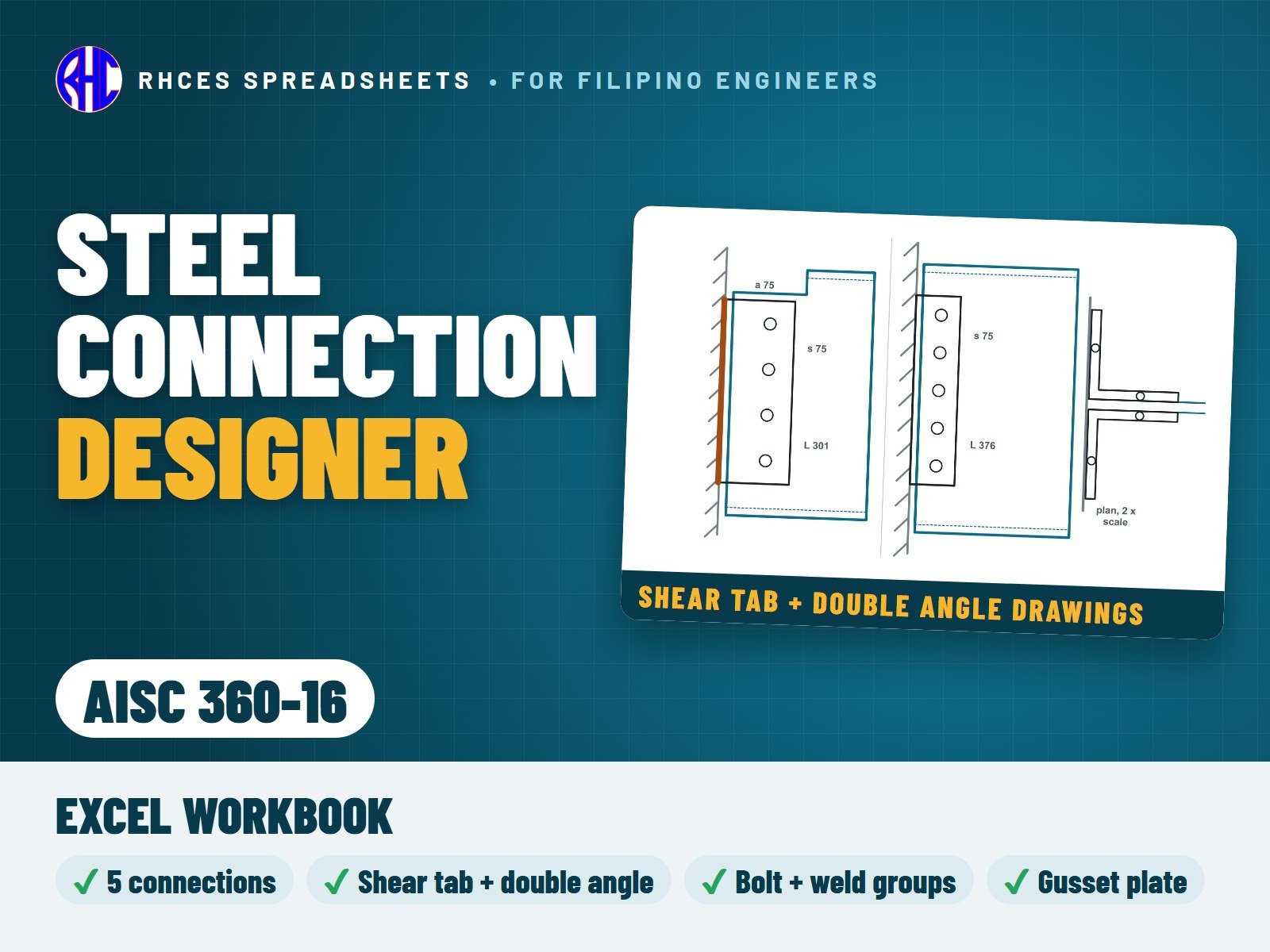
Check five common steel connections to AISC 360-16 for factored forces in LRFD, in one workbook: the single-plate shear tab and the all-bolted double-angle beam end connection (both with an optional coped top flange); the eccentric bolt group and the eccentric fillet-weld group loaded in their plane, by the instantaneous-centre method with the elastic method for comparison; and the brace gusset plate in tension and compression, for bolted angle braces and slotted HSS braces welded to the gusset, with an optional check of the gusset-to-support weld. Each connection has its own sheet with its inputs, a drawing of its bolt and weld layout and its checks; the Design Check Summary collects the five under one overall result.

Checks: bolt shear, bearing and tear-out, and slip resistance of slip-critical joints; bolt groups by the instantaneous-centre or the elastic method; fillet welds with the directional strength increase and the base metal; plate yielding, rupture and block shear; beam-web yielding, rupture and block shear; angle yielding, rupture and block shear; flexure of the coped section; gusset yielding and rupture on the Whitmore width, block shear, buckling and brace shear lag; the optional gusset interface weld. The Bolt Group takes up to 3 lines of 12 bolts, standard or oversized holes, snug-tight, pretensioned or slip-critical bolts and a load inclined 0 to 90 degrees; the Weld Group takes a single line, two vertical lines, two horizontal lines, a C-shape or a box. The gusset buckling length and K are typed by you.

The overall result reads CONNECTIONS ADEQUATE, ADEQUATE · SEE CHECKS, REVISE THE CONNECTIONS or INCOMPLETE DATA. Not covered: seismic connection requirements (the expected brace strength, for example), the local checks of the supporting members (column web and flange, girder web), double and long copes, the beam's own shear and flexure away from the connection, and ASD. The Read Me lists the items worth confirming.

References: ANSI/AISC 360-16 (July 7, 2016) with the strength combinations of ASCE/SEI 7-22 (the Read Me notes that AISC 360-16 lists ASCE/SEI 7-16), with the printed page of each Specification reference shown in the workbook. Not clauses of AISC 360-16 and marked so: the instantaneous-centre and elastic methods of eccentric bolt and weld groups, coped beams, the Whitmore section, the single-plate (Table 10-9) and double-angle practice and the gusset interface weld are AISC Manual methods; check them against the Manual edition you use.

Every result is a visible Excel formula, with printed AISC 360-16 clause and page references for the Specification items. Includes the Excel workbook. View sample on the store page previews a worked A4 sample calculation (five connections of a process building in Jubail Industrial City: a coped shear tab, a double-angle beam end, a crane-runway bracket with slip-critical bolts, a pipe-support bracket with C-shaped welds and an HSS brace gusset). One licence per engineer or office.
Excel · Shear Tab, Double Angle, Bolt Group, Weld Group, Gusset Plate + Summary (A4); View sample: 15 pages
₱449.00View sample
Preview of Steel Deck Slab Designer (NSCP 2015)
Steel

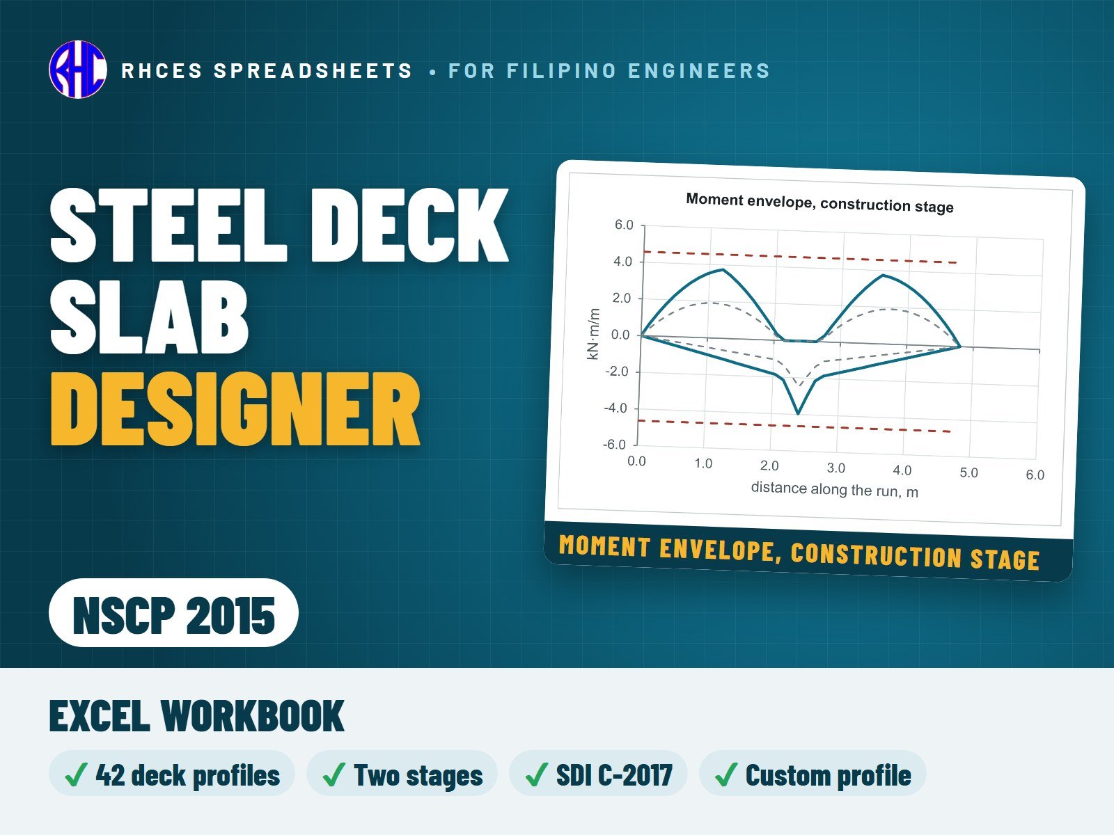
Steel Deck Slab Designer (NSCP 2015)

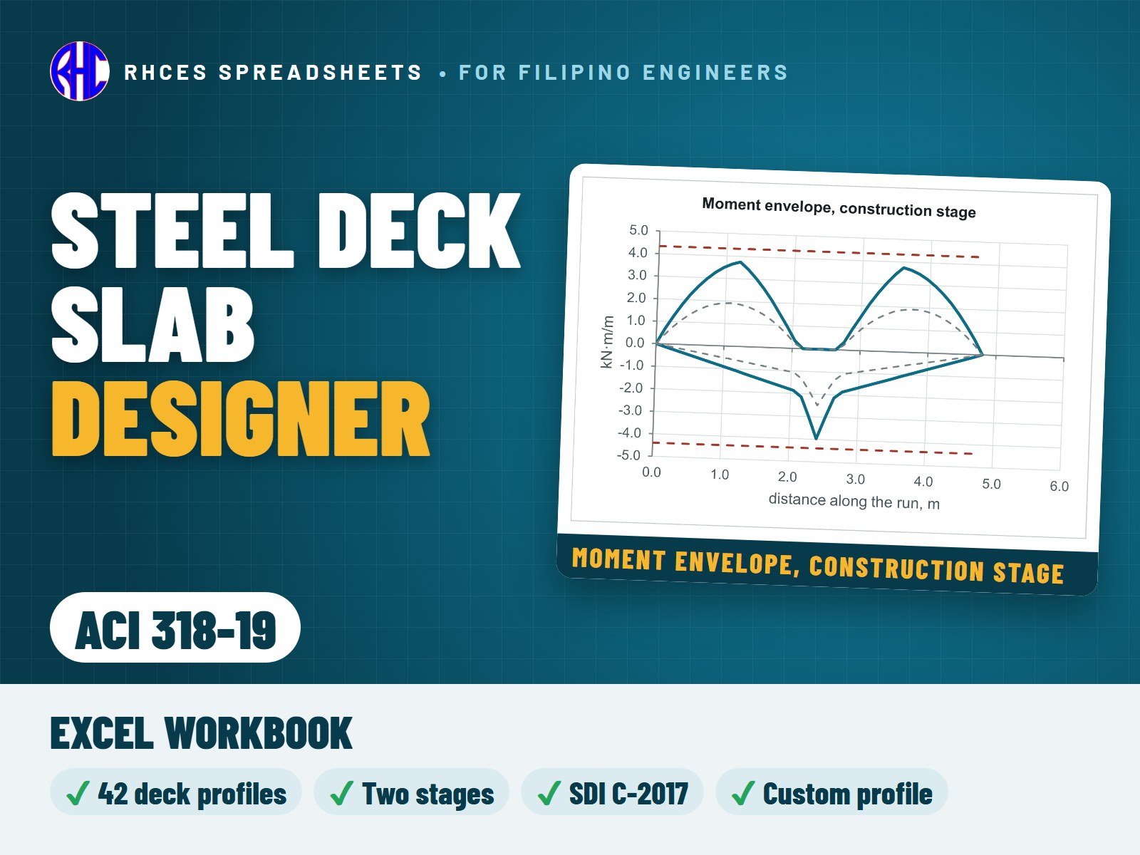
Design one composite steel deck slab panel (one deck run) in two stages by NSCP 2015: the deck as cold-formed steel by Sections 551 to 553 and the concrete and reinforcement by Chapter 4, with the construction loads and the composite slab rules of ANSI/SDI C-2017. Pick the deck from the library (42 rows: SDI generic profiles, ASC Steel Deck, Philmetal Products and Steeltech) or type a Custom profile from the maker's drawing, with the steel, the thickness and its basis (base metal or total coated). The deck library values are marked P (published), C (computed) or N (not published) with the document read in October 2026; they are not maker-verified, so confirm them against the maker's current catalogue before use.

Stage 1, the deck as a form while the concrete is placed: the SDI construction load cases on one to four or more spans, equal or unequal, with an optional end cantilever and optional or automatic shoring; deck flexure, shear, web crippling and their interactions, deflection, the maximum unshored span and the shore-line loads. LRFD, with ASD offered for this stage.

Stage 2, the hardened composite slab: flexure by the SDI Prequalified Section Method or the maker's declared strength (or, by choice, a reinforced concrete slab on the deck as a form only), one-way shear, deflection, a concentrated load (effective width, punching, weak-axis steel), temperature and shrinkage steel, top bars over the beams of a continuous slab, and the bars, shear and service deflection of an end cantilever. The deck items the beam designer needs (rib height and width, concrete above the deck, stud diameter and length, stud height above the deck, cover over the stud, deck anchorage) are listed against the AISC 360-16 stud and rib limits. Drawings redraw from your inputs: the deck profile, and the construction-stage spans with the moment envelope and deflection. The Design Check Summary collects every check under one overall result: STEEL DECK SLAB ADEQUATE, ADEQUATE · SEE CHECKS, REVISE THE DECK OR THE SLAB or INCOMPLETE DATA · SEE CHECKS.

Not covered: diaphragm design, fire rating, floor vibration, the composite beam itself (studs and beam strength; only the deck items are listed), SDI Appendix 3 (shear bond, needs the maker's test values) and Appendix 4 (ultimate strength with studs), C-2017 A2.2.2 (over-reinforced slabs, not implemented; the check is conservative), ASD for the composite stage, two-way slabs on deck, cellular, re-entrant and flat-pan decks, roof decks without concrete, openings and edge trims, and live-load reduction. The Read Me lists the items worth confirming.

References: NSCP 2015 (7th ed.) Chapter 4 (concrete and reinforcement), Chapter 5 Sections 551 to 553 (cold-formed steel) and Chapter 2 (loads), with the printed page of each reference shown in the workbook. NSCP 2015 gives no design rules for composite steel deck slabs (Section 401.4.9) and refers them to ASCE 3, whose current successor is ANSI/SDI C-2017, so the composite checks follow C-2017 and are marked "Not in NSCP - SDI" in the workbook. Also used and marked: ANSI/SDI C-2017, SDI Floor Deck Design Manual 2nd ed., AISI S100-16 w/ S3-22, AISC 360-16 (I3.2c, I8.1) and ASCE/SEI 37-14. The Read Me states each correction made to the printed NSCP text where it is used.

The method was checked against the worked examples of the SDI Floor Deck Design Manual (construction spans, unequal spans, composite section, shear and concentrated load) and against maker catalogue tables, and every number was compared with a second, independent calculation.

Every result is a visible Excel formula with the clause and page of each reference. Includes the Excel workbook. View sample on the store page previews a worked A4 sample calculation (17 pages: a 2nd-floor office slab on SDI generic 2 in. x 12 in. deck, 0.91 mm, over two 2.50 m spans, 125 mm slab, f'c 21 MPa; result STEEL DECK SLAB ADEQUATE, governed by deck web crippling at the interior beam while the concrete is placed). One licence per engineer or office.
Excel · Deck, Construction Stage, Composite Slab, Reinforcement and Summary sheets (A4); View sample: 17 pag
₱449.00View sample
Preview of Steel Deck Slab Designer (ACI 318-19)
Steel

Steel Deck Slab Designer (ACI 318-19)

Design one composite steel deck slab panel (one deck run) in two stages: the composite slab and the construction loads by ANSI/SDI C-2017, the deck as cold-formed steel by AISI S100-16, and the concrete and reinforcement by ACI 318-19 (SI units, loads by ASCE 7-16). Pick the deck from the library (42 rows: SDI generic profiles, ASC Steel Deck, Philmetal Products and Steeltech) or type a Custom profile from the maker's drawing, with the steel, the thickness and its basis (base metal or total coated). The deck library values are marked P (published), C (computed) or N (not published) with the document read in October 2026; they are not maker-verified, so confirm them against the maker's current catalogue before use.

Stage 1, the deck as a form while the concrete is placed: the SDI construction load cases on one to four or more spans, equal or unequal, with an optional end cantilever and optional or automatic shoring; deck flexure, shear, web crippling and their interactions, deflection, the maximum unshored span and the shore-line loads. LRFD, with ASD offered for this stage.

Stage 2, the hardened composite slab: flexure by the SDI Prequalified Section Method or the maker's declared strength (or, by choice, a reinforced concrete slab on the deck as a form only), one-way shear, deflection, a concentrated load (effective width, punching, weak-axis steel), temperature and shrinkage steel, top bars over the beams of a continuous slab, and the bars, shear and service deflection of an end cantilever. The deck items the beam designer needs (rib height and width, concrete above the deck, stud diameter and length, stud height above the deck, cover over the stud, deck anchorage) are listed against the AISC 360-16 stud and rib limits. Drawings redraw from your inputs: the deck profile, and the construction-stage spans with the moment envelope and deflection. The Design Check Summary collects every check under one overall result: STEEL DECK SLAB ADEQUATE, ADEQUATE · SEE CHECKS, REVISE THE DECK OR THE SLAB or INCOMPLETE DATA · SEE CHECKS.

Not covered: diaphragm design, fire rating, floor vibration, the composite beam itself (studs and beam strength; only the deck items are listed), SDI Appendix 3 (shear bond, needs the maker's test values) and Appendix 4 (ultimate strength with studs), C-2017 A2.2.2 (over-reinforced slabs, not implemented; the check is conservative), ASD for the composite stage, two-way slabs on deck, cellular, re-entrant and flat-pan decks, roof decks without concrete, openings and edge trims, and live-load reduction. The Read Me lists the items worth confirming.

References: ANSI/SDI C-2017 for the composite slab and the construction loads; AISI S100-16 w/ S3-22 for the deck; ACI 318M-19 for the concrete and reinforcement (ACI 318-19 excludes composite deck slabs, 1.4.10, so SDI governs them); ASCE 7-16 for the loads; also the SDI Floor Deck Design Manual 2nd ed., AISC 360-16 (I3.2c, I8.1) and ASCE/SEI 37-14, with the printed page of each reference shown in the workbook. NSCP 2015 is not used in this edition.

The method was checked against the worked examples of the SDI Floor Deck Design Manual (construction spans, unequal spans, composite section, shear and concentrated load) and against maker catalogue tables, and every number was compared with a second, independent calculation.

Every result is a visible Excel formula with the clause and page of each reference. Includes the Excel workbook. View sample on the store page previews a worked A4 sample calculation (17 pages: a 2nd-floor office slab on SDI generic 2 in. x 12 in. deck, 0.91 mm, over two 2.50 m spans, 125 mm slab, f'c 21 MPa; result STEEL DECK SLAB ADEQUATE, governed by deck web crippling at the interior beam while the concrete is placed). One licence per engineer or office.
Excel · Deck, Construction Stage, Composite Slab, Reinforcement and Summary sheets (A4); View sample: 17 pag
₱449.00View sample
Preview of Blast-Resistant Member Designer (SDOF)
Steel

Blast-Resistant Member Designer (SDOF)

Design one blast-loaded member as an equivalent single-degree-of-freedom (SDOF) system: a reinforced-concrete wall or slab panel (a 1 m strip), a rectangular reinforced-concrete beam, or a hot-rolled steel I-section used as a beam, girt or purlin, with simple, fixed, propped or cantilever supports, under a uniformly distributed pressure pulse and uniform mass. The default criteria are ASCE/SEI 59-11 (response limits by expected damage: Superficial, Moderate, Heavy or Hazardous). The option General applies the ASCE (2010) guide for petrochemical facilities with UFC 3-340-02, with response levels Low, Medium, High or User (type your project's own limits).

Blast Load: from the side-on blast data of the project (peak overpressure with duration or impulse, and the building dimensions) the sheet works out the pressure pulse on the front wall (reflection and clearing), side wall, roof or rear wall (equivalent load factor, drag, rise time), or you type the pressure pulse of the member yourself, with an optional negative phase. A live drawing shows the pulse.

Member: the dynamic material strengths (strength and dynamic increase factors), the flexural and shear resistance, the detailing checks, the stiffness, the mass, the transformation factors and the natural period. Reinforced-concrete sections of Type I or Type II; steel I-sections with the plastic moment and the compactness check. Direct shear and diagonal tension, the connection design forces and the rebound are checked.

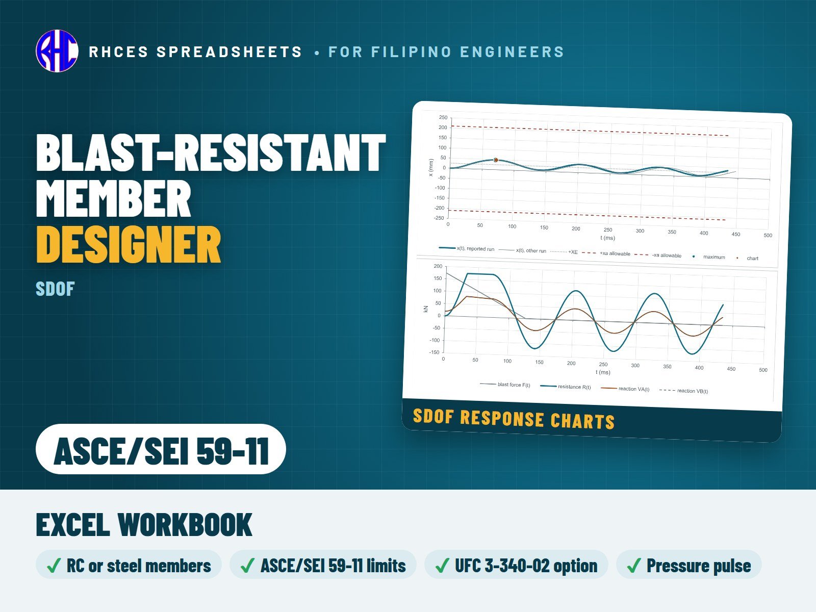
SDOF Response: a step-by-step time history of 2,500 steps per run (two runs, one with the elastic load-mass factor and one with the factor of your option), checked against the Biggs elasto-plastic chart. It compares the support rotation and the ductility with the limits of the set and gives the dynamic reactions and the connection design forces. Live drawings show the member, its resistance function and the response. The Design Check Summary ends in one overall result: MEMBER ADEQUATE, OK · SEE CHECKS, REVISE MEMBER or INCOMPLETE DATA · SEE CHECKS.

Not covered: blast load generation from a charge, TNT equivalence and vapour-cloud models (the blast data are inputs); MDOF and finite-element models, frame sidesway, global stability and foundations; two-way panels; masonry; prestressed members, double tees and T-beams; cold-formed panels, girts and purlins; open-web joists; steel plates; blast doors and windows; point loads and non-uniform loads; tension-membrane action; composite action; near-field and high-pressure effects, breach, spall and fragments; connection design beyond the reactions (bolts, welds, embeds, anchors). The Read Me lists the assumptions, the limits and the items to verify, and says which rules are readings of this tool.

References: ASCE/SEI 59-11, Blast Protection of Buildings (2011); ASCE, Design of Blast-Resistant Buildings in Petrochemical Facilities, 2nd ed. (2010); UFC 3-340-02, Structures to Resist the Effects of Accidental Explosions (2008, Change 2, 2014); ACI 318M-19 for the member strength; also the Handbook for Blast-Resistant Design of Buildings (Dusenberry, 2010), the JRC report EUR 26456 and Biggs, Introduction to Structural Dynamics. Each is cited by section, table, figure, equation or printed page in the workbook.

The method was checked against the published answers of the ASCE guide (front wall, roof load and Appendix 3), the Handbook wind-girt example, the Biggs chart at its published points and the UFC 3-340-02 tables, and against an independent fine-step solution.

Every result is a visible Excel formula. Includes the Excel workbook. View sample on the store page previews a worked A4 sample calculation (10 pages: a precast reinforced-concrete wall panel of a control building, front wall, designed with ASCE/SEI 59-11 at Moderate damage; 250 mm thick, f'c 28 MPa, T16 bars at 150 mm on both faces with T10 ties, simply supported over 6.0 m; side-on overpressure 13.8 kPa for 200 ms; the panel resists 174 kN per metre and responds with a ductility of 1.9 and a support rotation of 0.92 deg against the 4 deg limit; result MEMBER ADEQUATE). The sample is illustrative. One licence per engineer or office.

Excel · Blast Load, Member, SDOF Response and Summary sheets (A4); View sample: 10 pages
₱449.00View sample
Preview of Roof Framing Designer (NSCP 2015)
Steel

Roof Framing Designer (NSCP 2015)

Design the roof framing of one steel gable roof on angle trusses by NSCP 2015 (7th edition, SI), in one linked workbook: the roofing-sheet screws, the cold-formed purlins and sag rods, the steel truss analysis and its members, the joints, and the supports with their anchor rods. Wind comes from the roof geometry (MWFRS and components and cladding by zone), the purlin reactions load the truss, the truss forces size every member and joint, and the reactions go to the anchors; change one input and every sheet follows.

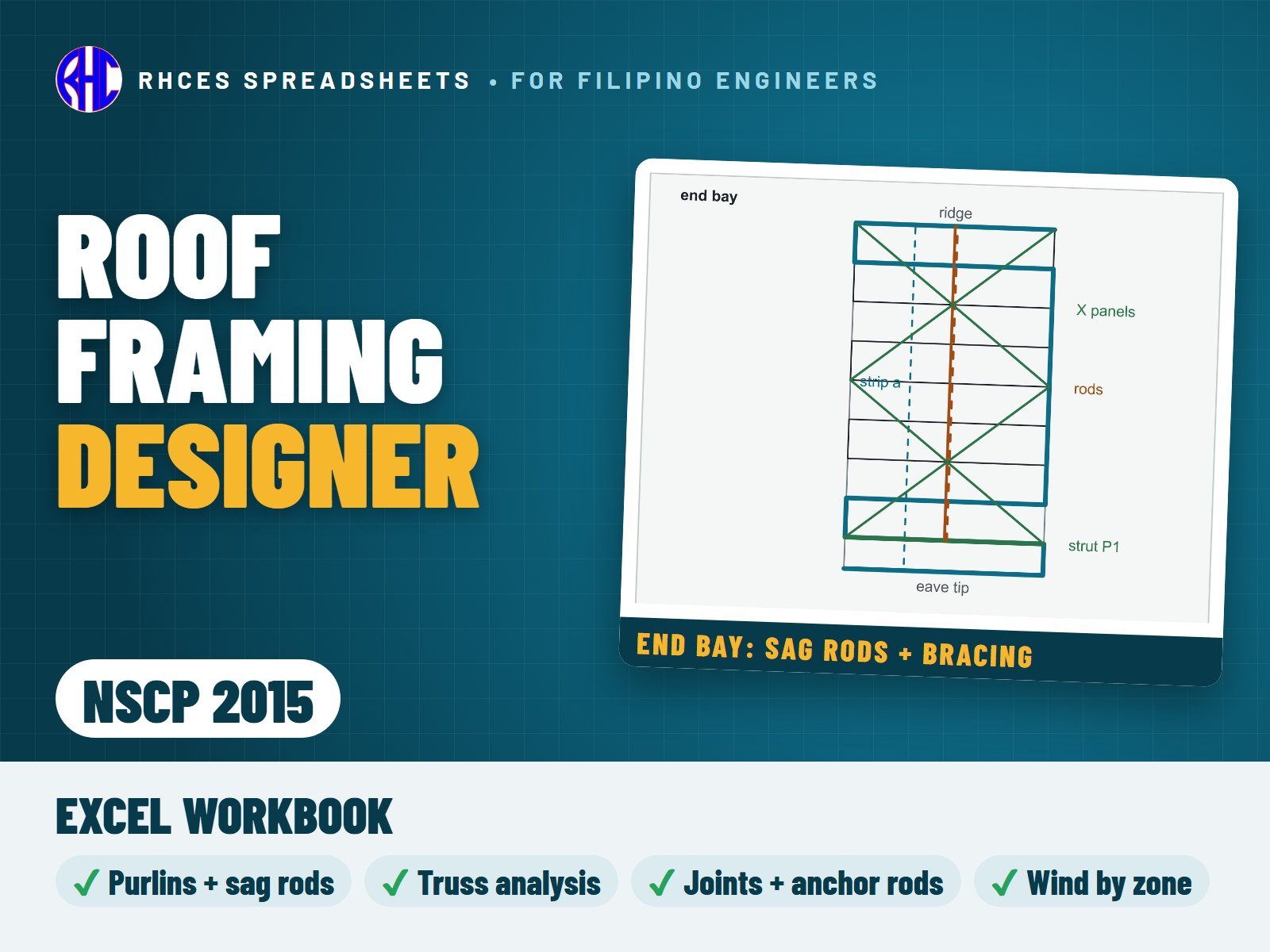
Purlins and sag rods: lipped C or lipped Z, simple or lapped continuous spans, from a library of Philippine stock sections or typed; black and pre-galvanized steels (ASTM, AS, JIS) or a typed Fy and Fu; sheet and purlin thickness as base metal (BMT) or total coated (TCT); gravity and wind uplift on every purlin line, the R-factor route of 554.6.1.1 with automatic routing to a rational analysis, weak axis between sag rods, shear and web crippling, deflection, the purlin anchorage of 554.6.3.1, sag rods of 10, 12 or 16 mm, the ridge tie, the end-bay X-bracing as a wind girder and the eave strut. Sheets and screws: pull-out, pull-over and shear, with conditions 9 to 13 of 554.6.1.1.

Truss and members: compound Fink, Fink, Howe, Pratt, pitched Warren, mono-pitch or a Custom form; single angles and double angles back to back, bolted or welded ends, stitches, bottom-chord ties, angle X-bracing; every load combination of 203.3.1 with the envelope per member; tension, compression, the top chord with bending from the purlins, and deflection against IBC 2009 Table 1604.3. Joints: bolt groups, fillet-weld groups, the heel joint, gussets with the Whitmore section and block shear, chord splices and the apex, the purlin cleat, the cleats of the eave strut and the end-bay strut, and the lug of the X-rods. Supports: bearing plate, grout pad, the anchor rods (cast-in and post-installed types) with breakout, pullout, side-face blowout and bond in tension, breakout and pryout in shear, the interaction of 417.6, the slotted end and the heel weld, checked in every combination at both ends. All checks are listed in the Design Check Summary (113 rows) with demand, capacity, ratio and status under one overall result: ROOF FRAMING ADEQUATE, ADEQUATE · SEE CHECKS, REVISE THE ROOF FRAMING or INCOMPLETE DATA — SEE CHECKS. Drawings of the sheet profile, the purlin section, the end bay and the support plate are in the workbook.

Not covered: portal frames, standing-seam, monoslope, hip and troughed roofs, gable overhangs, unequal spans, scissor, bowstring and parallel-chord trusses, members other than angles, slip-critical joints, fatigue, earthquake loads on the truss (except the collector force of the eave strut and the end-bay seats), the design of the sheet itself (the maker's tables), the design of the column, and base plates under moment.

References: NSCP 2015 (7th edition, 1st printing), with the page of each reference shown in the workbook; ACI 318M-14 where NSCP Section 417 relies on it; IBC 2009 Table 1604.3 for deflection limits; ASTM, AS and JIS steel grades and maker data for sheets and screws, listed in the Read Me. Three printed pages of our copy of the NSCP (2-27, 2-28 and 4-107) were unavailable; the workbook states where each is used and what it uses instead.

Checks run on the workbook: automated runs of more than 6 million checks (random and wide cases, blank and zero inputs, every drop-down value) ended with no problem; the sample's roof loads were re-derived from the printed NSCP in a separate script and agree within 0.1 % on pressures and 0.03 % on forces; and the truss analysis was compared with an independent ETABS 22 model: 3,213 member forces (27 members in 119 load combinations) agree to rounding.

Every result is a visible Excel formula. Includes the Excel workbook. View sample on the store page previews a worked A4 sample calculation (74 pages: roof R-1 of the one-storey shop RF-1 in Metro Manila, 12.0 x 24.0 m, seven trusses at 4.0 m, rise 2.0 m, V = 260 km/h, Exposure C; result ROOF FRAMING ADEQUATE, governing check purlin line P2 in uplift at 0.994, top chord 2L75x75x9, 12 mm sag rods, 24 mm X-rods, 16 mm anchor rods on a 400 x 400 mm column top). The sample is illustrative; the basic wind speed is a reading of the wind map, to be confirmed for the real site. Companion of the e-book Roof Framing Design Made Clear (NSCP 2015) on library.rhces.com; both are also sold together in the Roof Framing Bundle (Bundles). One licence per engineer or office.

Excel · Loads, Purlin, Sag Rod, Truss, Members, Joints, Supports and Summary sheets (A4); View sample: 74 pa
₱1,499.00View sample
1Click Buy now
2Pay by GCash, Maya or QR Ph on PayMongo’s secure page, or with PayPal
3Your Download button appears as soon as payment clears