RHCES Spreadsheets

Spreadsheets that do the work.

Buy in one click, pay by GCash, Maya, QR Ph or PayPal, and your download appears as soon as the payment clears.

All products are non-refundable. Please check the details and price before you pay.
Licensed to the buyer only (one engineer or office). Sharing, uploading or reselling a product, or forwarding its download link, without the written permission of RHCES is prohibited. By buying you agree to our Terms of Service.

Preview of RC Beam Section Designer (NSCP 2015)
Structural

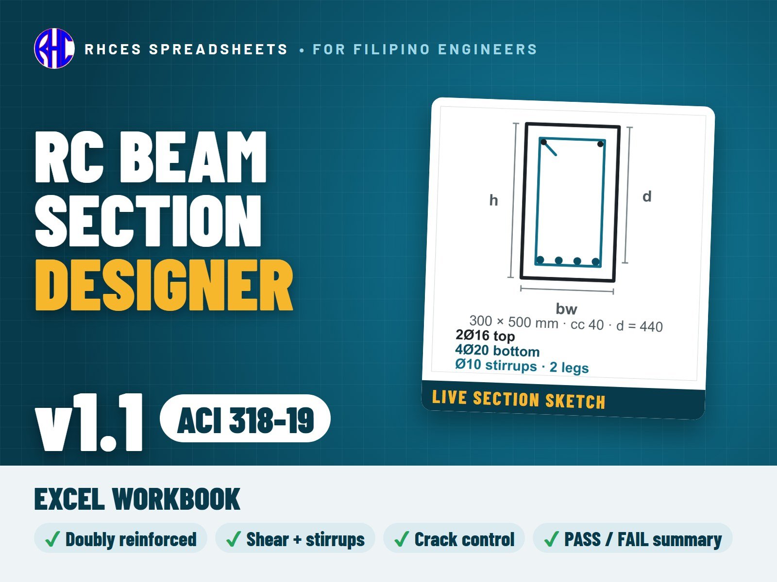
RC Beam Section Designer (NSCP 2015)

Check a rectangular reinforced-concrete beam section to NSCP 2015 in minutes. Enter the materials, section, bars and the factored Mu and Vu, and the sheet works out the rest.

Flexure for singly or doubly reinforced beams, with tension bars placed in one or two layers automatically and the compression-steel stress found whether it yields or not. Ductility (net tensile strain and phi), minimum steel, shear with vertical stirrups, maximum stirrup spacing, minimum stirrups, bar clear spacing, crack-control spacing and the minimum-depth (deflection) rule.

A design check summary shows demand, capacity, ratio and PASS / FAIL for every check, with one overall result. Design aids give the required steel area and stirrup spacing so you can size the bars quickly.

Every result is an open Excel formula with readable names, and the code-based steps carry NSCP 2015 clause references. Prints as a clean 3-page A4 calculation sheet with your project details.

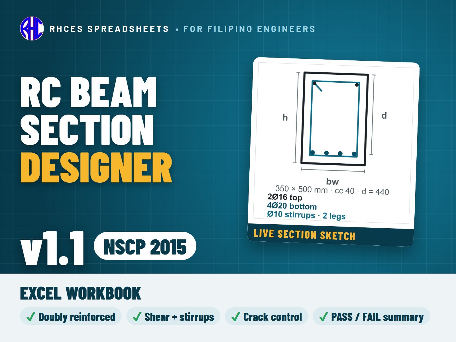
Version 1.1 (October 2026): the section drawing is now live, redrawn from your bars and layers as you type. Results are unchanged from version 1.0. Entries outside the allowed ranges are refused, and an incomplete set of inputs shows CHECK INPUTS instead of a verdict. Bars that do not fit in their layer are drawn in red.

Includes the Excel workbook. A worked A4 sample calculation can be previewed with View sample on the store page. One licence per engineer or office.

Learning the method? The e-book RC Beam Design Made Clear (NSCP 2015) works through it step by step; it is sold separately on library.rhces.com.
Excel · 3-page A4 calc sheet · open formulas · v1.1
₱399.00View sample
Preview of RC Beam Section Designer SMRF (NSCP 2015)
Structural

RC Beam Section Designer SMRF (NSCP 2015)

Design a beam of a special moment frame (SMRF) to NSCP 2015 Section 418.6. The Beam Design sheet checks the midspan section like the regular RC Beam Section Designer (flexure, singly or doubly reinforced in one or two layers, ductility, minimum steel, shear, cover, bar spacing, crack control and minimum depth), and the SMRF Beam sheet adds the special moment frame rules at both column faces.

SMRF checks: materials for special seismic systems (fy and fyt at most 420 MPa); the size limits of 418.6.2; the longitudinal steel of 418.6.3 at six sections (top and bottom at the left face, midspan and right face): two continuous bars, minimum steel, steel ratio at most 0.025, M+n at a face at least half of M-n and every section at least a quarter of the largest Mn; probable moments Mpr (1.25 fy, phi = 1.0) and the design shear Ve from Mpr for both sway directions with the gravity load 1.2D + 1.0L (418.6.5), with Vc = 0 in the hoop zones where the code requires it; hoops over 2h from each face with the first hoop within 50 mm and spacing at most d/4, 6 db and 150 mm (418.6.4); and the beam-bar checks at the joints (20 db through an interior joint, hooked-bar development in an exterior joint, 418.8).

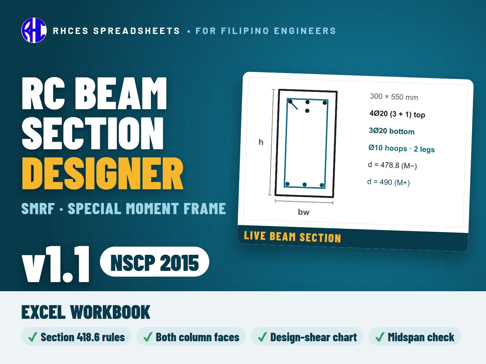
A live elevation shows the hoop zones and bars, and a chart shows the design shear along the span. The check summary gives demand, capacity, ratio and PASS / FAIL for every line, with one overall result. Cross-checked against the special moment frame girder example of FEMA 451 (within 0.5 %).

Not covered: the columns, joint shear and strong column / weak beam (see the RC Column Section Designer SMRF), T-beam action and torsion.

Every result is a visible Excel formula with printed NSCP 2015 clause and page references. Includes the Excel workbook. A worked A4 sample calculation can be previewed with View sample on the store page. One licence per engineer or office.

Version 1.1 (October 2026): the Beam Design sheet and the SMRF Beam sheet now draw the live section of your bars and layers (left face, midspan and right face). Results are unchanged from version 1.0. Bars that do not fit in their layer are drawn in red.

Excel · A4 calc sheets + live beam elevation & design-shear chart · v1.1
₱449.00View sample
Preview of RC Column Section Designer (NSCP 2015)
Structural

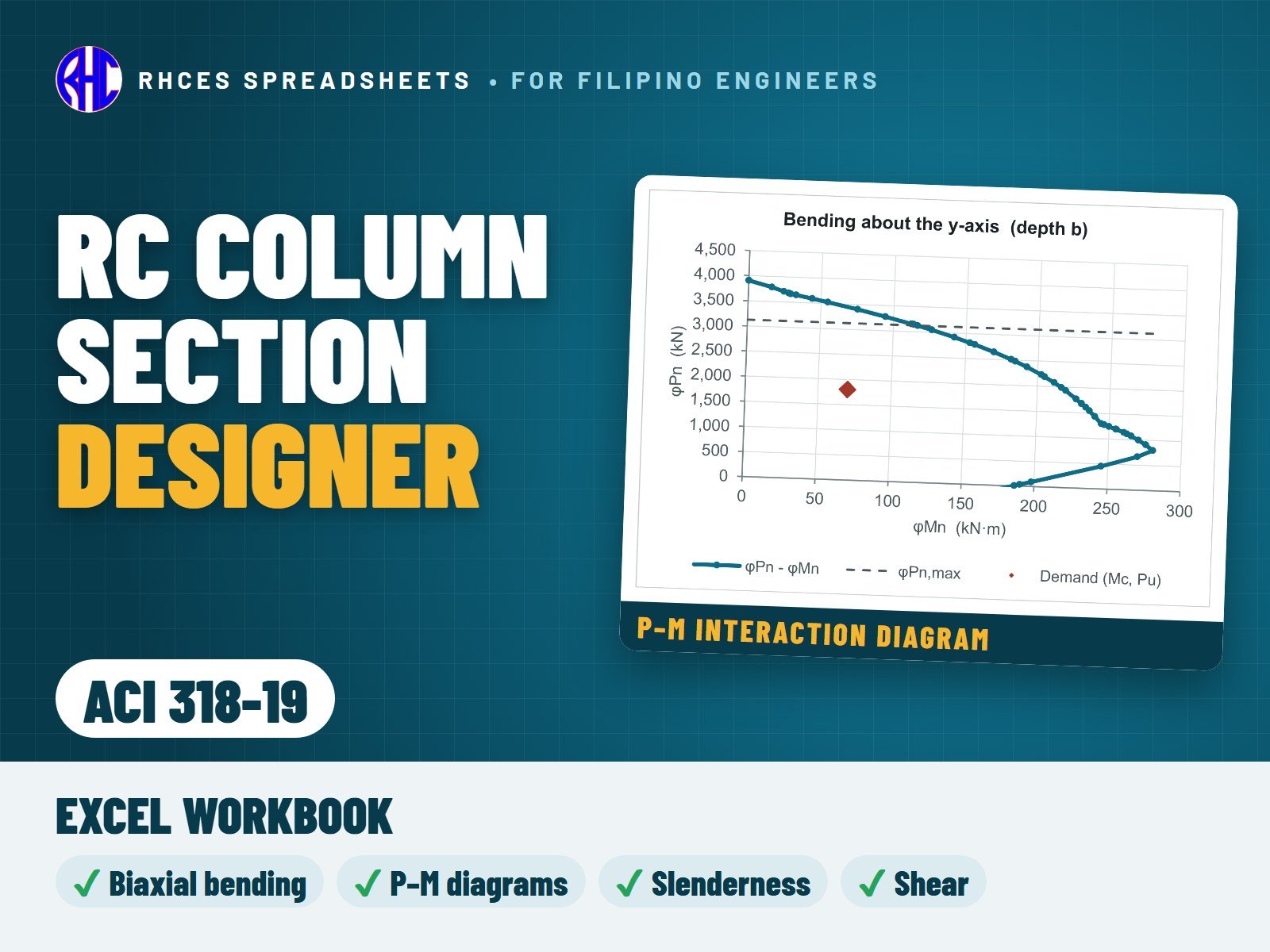
RC Column Section Designer (NSCP 2015)

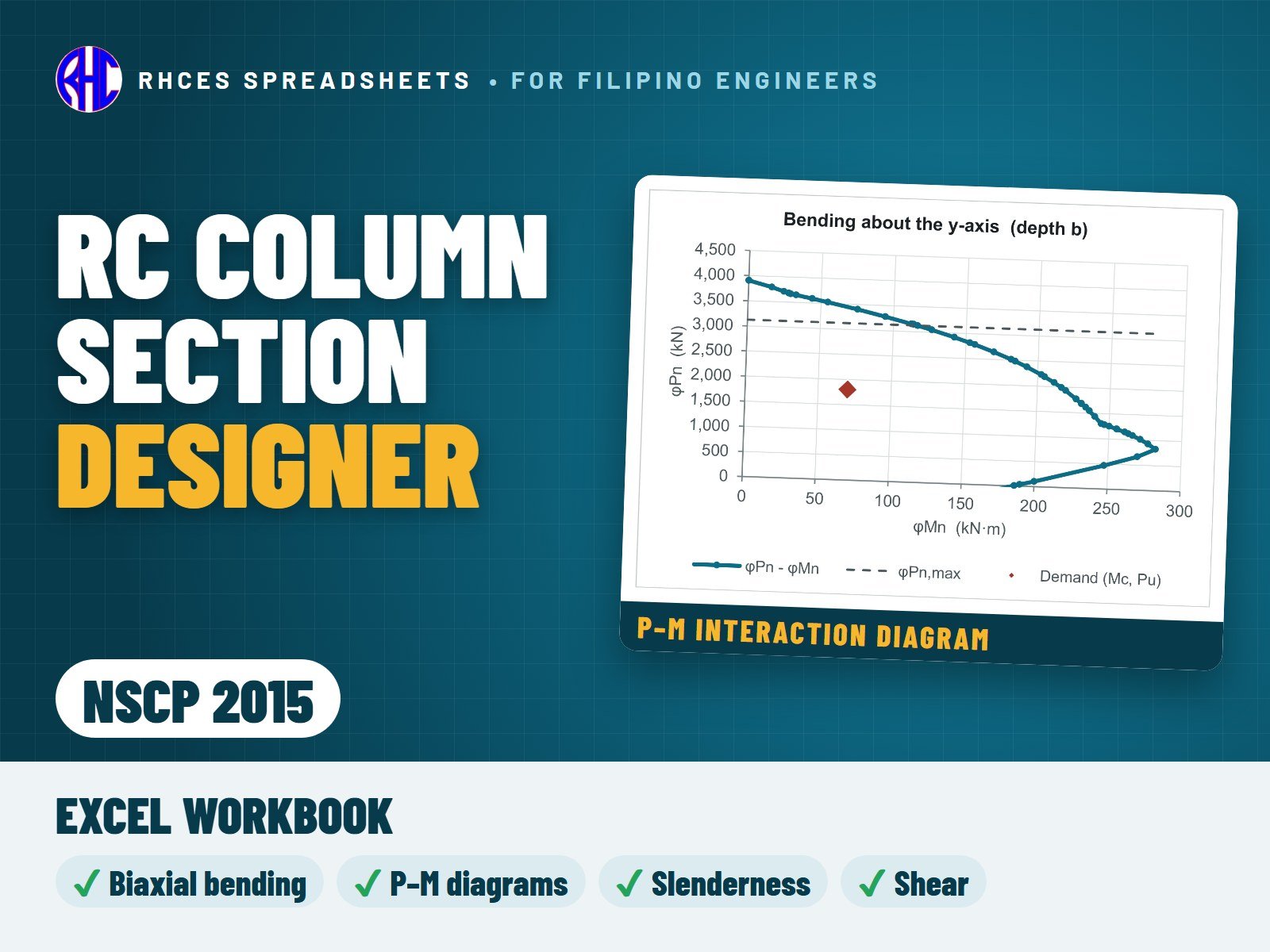
Design and check a rectangular tied reinforced-concrete column to NSCP 2015: axial load with bending about both axes, slenderness and shear, with interaction diagrams drawn for you.

The P–M interaction diagram for each axis is built by strain compatibility over every bar layer and plotted as a chart with your load point on it. The sheet reads the design moment capacity at your factored axial load and checks biaxial bending with the load-contour method, plus the 0.80 Po axial limit.

Slenderness per axis: braced columns get the full moment magnification (with the minimum moment), sway columns are flagged for second-order moments, and unstable columns are caught. Curvature is picked from a drop-down, so the NSCP sign rule is applied for you.

Shear in both directions with the axial-load benefit, and detailing checks: steel ratio 1–8 %, minimum bars, bar clear spacing, tie size, tie spacing and crossties.

A design check summary shows demand, capacity, ratio and PASS / FAIL for every check, with one overall result. Every result is a visible Excel formula with NSCP 2015 clause references; prints as a clean A4 calculation (4 pages + interaction diagrams). Ordinary (non-seismic) detailing; special moment frame (Section 418) confinement is not covered in this version.

Includes the Excel workbook. A worked A4 sample calculation can be previewed with View sample on the store page. One licence per engineer or office.

Learning the method? The e-book RC Column Design Made Clear (NSCP 2015) works through it step by step; it is sold separately on library.rhces.com.
Excel · A4 calc sheet + P–M interaction diagrams
₱399.00View sample
Preview of RC Column Section Designer SMRF (NSCP 2015)
Structural

RC Column Section Designer SMRF (NSCP 2015)

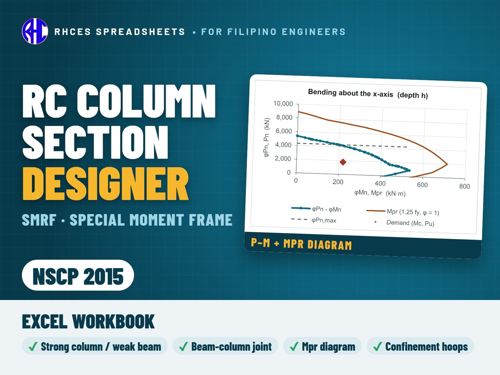
Design and check a rectangular tied column of a special moment frame (SMRF) to NSCP 2015 Section 418.7, with the beam-column joint at its top (418.8). It keeps everything of the regular RC Column Section Designer (biaxial P-M interaction by strain compatibility, slenderness and moment magnification, shear with axial load, cover and detailing) and adds the special moment frame rules.

SMRF checks: materials (bars fy at most 420 MPa; hoops up to 700 MPa for confinement); least dimension at least 300 mm and aspect ratio at least 0.4; steel ratio 1 to 6 %; strong column / weak beam, sum of Mnc at least 6/5 of the sum of Mnb in both sway directions (slab bars included); the confinement length lo, hoop spacing and the Ash rules of 418.7.5, and the spacing beyond lo; the design shear Ve from the probable moments Mpr (1.25 fy, phi = 1.0) over the axial range Pu,min to Pu, limited by the Mpr of the beams, with Vc = 0 where the code requires it; lap splices in the centre half of the clear height; axial tension under the smallest axial load; and joint shear Vj against phi Vn with the 1.7 / 1.2 / 1.0 factors, plus the 20 db and hooked-bar rules.

The Interaction sheet plots the phi Pn - phi Mn curve of each axis, the Mpr curve and your load point; a column elevation drawn to scale shows lo, the hoops and the splice zone. The check summary gives demand, capacity, ratio and PASS / CHECK / FAIL for every line, with one overall result.

Not covered: circular or spiral columns, precast frames, intermediate or ordinary moment frames, and the beam design of 418.6 (see the RC Beam Section Designer SMRF).

Every result is a visible Excel formula with printed NSCP 2015 clause and page references. Includes the Excel workbook. A worked A4 sample calculation can be previewed with View sample on the store page. One licence per engineer or office.

Excel · A4 calc sheets + P–M and Mpr interaction diagrams + column elevation
₱449.00View sample
Preview of RC Beam Section Designer (ACI 318-19)
Structural

RC Beam Section Designer (ACI 318-19)

Check a rectangular reinforced-concrete beam section to ACI 318-19 (SI units) in minutes. Enter the materials, section, bars and the factored Mu and Vu, and the sheet works out the rest.

Flexure for singly or doubly reinforced beams, with tension bars placed in one or two layers automatically and the compression-steel stress found whether it yields or not. Ductility to ACI 318-19 (net tensile strain at least the yield strain + 0.003, with the matching phi), minimum steel, bar clear spacing, crack-control spacing and the minimum-depth (deflection) rule.

Shear uses the ACI 318-19 concrete shear table step by step: the simple formula, the formula with the longitudinal steel ratio, and the size-effect formula when stirrups are below the minimum, with the upper limit and a note showing which case governs. Then stirrup strength, the section limit, maximum spacing and minimum stirrups.

A design check summary shows demand, capacity, ratio and PASS / FAIL for every check, with one overall result. Every result is an open Excel formula with readable names and ACI 318-19 clause references, and it prints as a clean 3-page A4 calculation sheet.

Version 1.1 (October 2026): the section drawing is now live, redrawn from your bars and layers as you type. Results are unchanged from version 1.0. Entries outside the allowed ranges are refused, and an incomplete set of inputs shows CHECK INPUTS instead of a verdict. Bars that do not fit in their layer are drawn in red.

Includes the Excel workbook. A worked A4 sample calculation can be previewed with View sample on the store page. One licence per engineer or office. Looking for the Philippine code? See the NSCP 2015 edition.

Excel · 3-page A4 calc sheet · SI units · open formulas · v1.1
₱399.00View sample
Preview of RC Column Section Designer (ACI 318-19)
Structural

RC Column Section Designer (ACI 318-19)

Design and check a rectangular tied reinforced-concrete column to ACI 318-19 (SI units): axial load with bending about both axes, slenderness and shear, with interaction diagrams drawn for you.

The P–M interaction diagram for each axis is built by strain compatibility over every bar layer and plotted as a chart with your load point on it, using the ACI 318-19 strength reduction factors. The sheet reads the design moment capacity at your factored axial load and checks biaxial bending with the load-contour method, plus the 0.80 Po axial limit.

Slenderness per axis with moment magnification for braced columns (including the minimum moment), sway columns flagged for second-order moments, and unstable columns caught. Curvature is picked from a drop-down, so the code sign rule is applied for you.

Shear in both directions with the ACI 318-19 concrete shear table, including the axial-load term, the longitudinal-steel and size-effect formulas and the upper limit, plus minimum shear ties. Detailing checks: steel ratio 1–8 %, minimum bars, bar spacing, tie size (No. 13 for larger bars), tie spacing and crossties.

Every result is a visible Excel formula with ACI 318-19 clause references; prints as a clean A4 calculation. Ordinary (non-seismic) detailing; special moment frames (Chapter 18) are not covered in this version.

Includes the Excel workbook. A worked A4 sample calculation can be previewed with View sample on the store page. One licence per engineer or office. Looking for the Philippine code? See the NSCP 2015 edition.

Excel · A4 calc sheet + P–M interaction diagrams · SI units
₱399.00View sample
Preview of RC Circular Column Designer (NSCP 2015)
Structural

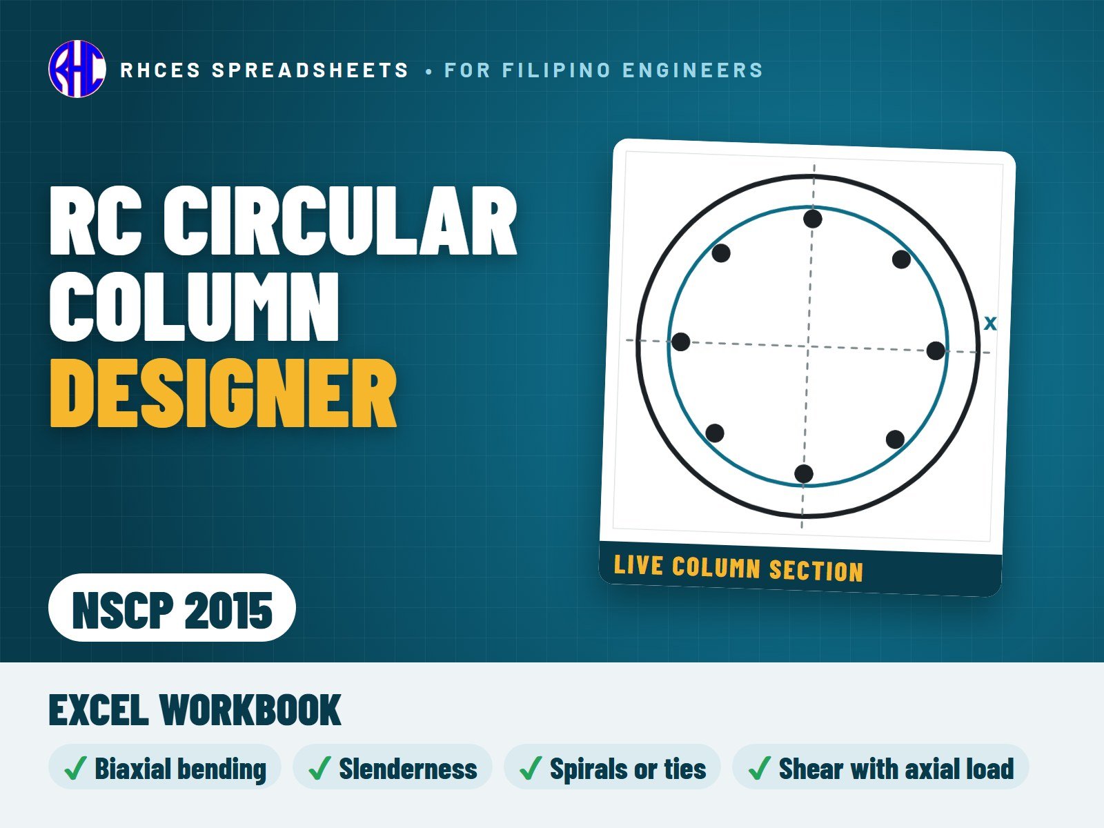
RC Circular Column Designer (NSCP 2015)

Design a solid circular reinforced-concrete column to NSCP 2015: axial load with biaxial bending (combined as the resultant moment), slenderness and moment magnification for braced frames (with the 1.4 second-order limit), P-M interaction by strain compatibility on a circular compression zone with the bars equally spaced on one circle, shear with axial load, and the longitudinal-bar, spiral and circular-tie detailing limits of Sections 410 and 425, with the zone 4 limits for columns outside the seismic-force-resisting system (418.14).

Enter the diameter, cover, materials, bars and the factored loads (several load rows); the sheet draws the live P-M interaction diagram with your load points, checks capacity, spiral or tie size and pitch, bar spacing and cover, and gives one overall result. Companion to the RC Column Section Designer (rectangular).

Every result is a visible Excel formula with NSCP 2015 clause references. Includes the Excel workbook. A worked A4 sample calculation can be previewed with View sample on the store page. One licence per engineer or office.

Excel · A4 calc sheet + P–M interaction diagram
₱399.00View sample
Preview of RC Circular Column Designer (ACI 318-19)
Structural

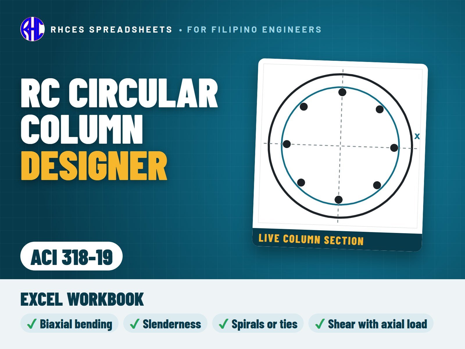
RC Circular Column Designer (ACI 318-19)

Design a solid circular reinforced-concrete column to ACI 318-19 (SI units): axial load with biaxial bending (combined as the resultant moment), slenderness and moment magnification for braced frames (with the 1.4 second-order limit), P-M interaction by strain compatibility on a circular compression zone with the bars equally spaced on one circle, shear with axial load, and the longitudinal-bar, spiral and circular-tie detailing limits of Chapters 10 and 25, with the ACI 318-19 phi transition and the Table 22.5.5.1 shear strength.

Enter the diameter, cover, materials, bars and the factored loads (several load rows); the sheet draws the live P-M interaction diagram with your load points, checks capacity, spiral or tie size and pitch, bar spacing and cover, and gives one overall result. Companion to the RC Column Section Designer (rectangular).

Every result is a visible Excel formula with ACI 318-19 section references. Includes the Excel workbook. A worked A4 sample calculation can be previewed with View sample on the store page. One licence per engineer or office. Looking for the Philippine code? See the NSCP 2015 edition.

Excel · A4 calc sheet + P–M interaction diagram · SI units
₱399.00View sample
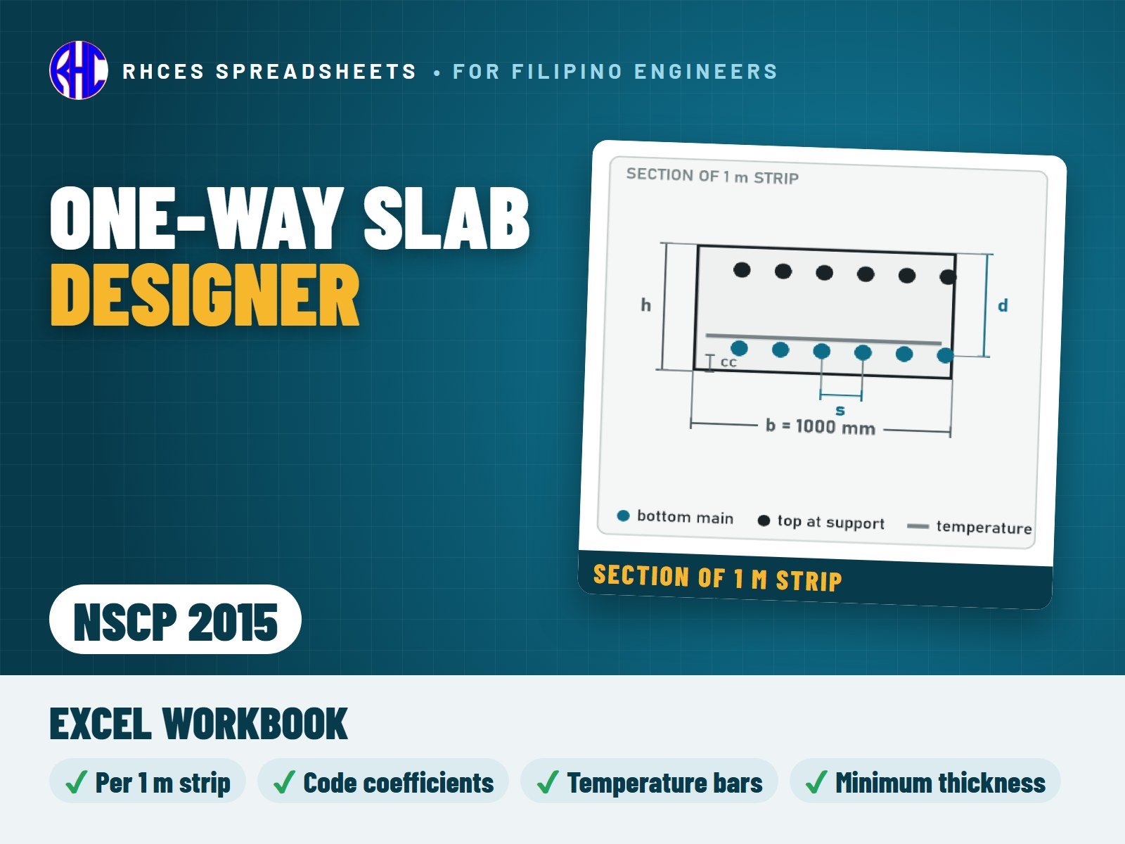
Preview of One-Way Slab Designer (NSCP 2015)
Structural

One-Way Slab Designer (NSCP 2015)

Design a solid one-way reinforced-concrete slab to NSCP 2015 per 1 m strip, from loads to bar spacing.

Self-weight is worked out for you; the factored load uses the larger of 1.4D and 1.2D + 1.6L. Moments and shear come from your choice: simply supported, cantilever, the NSCP 406.5 coefficients for continuous slabs (all positive and negative moment locations, with the 1.15 shear factor), or values typed in from your own analysis.

Checks bottom and top main bars for strength, ductility, minimum steel, maximum spacing, crack control and clear spacing; temperature and shrinkage bars; one-way shear without stirrups; and minimum thickness for deflection. Design aids give the required steel and the largest bar spacing that works.

A design check summary shows demand, capacity, ratio and PASS / FAIL for every check, with one overall result. Every result is a visible Excel formula with NSCP 2015 clause references; prints as a clean 2-page A4 calculation sheet.

Includes the Excel workbook. A worked A4 sample calculation can be previewed with View sample on the store page. One licence per engineer or office.

Excel · 2-page A4 calc sheet · per 1 m strip
₱249.00View sample
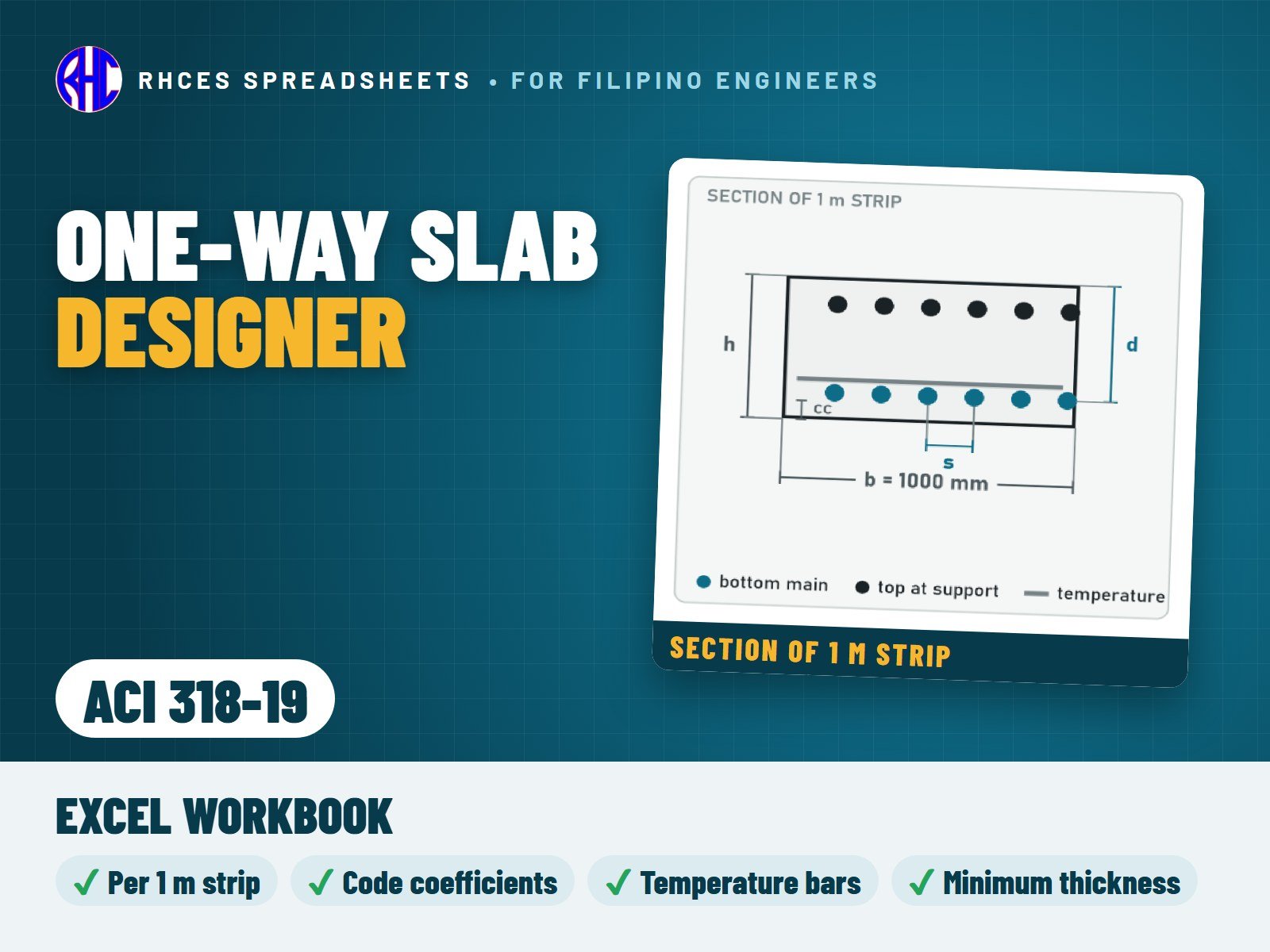
Preview of One-Way Slab Designer (ACI 318-19)
Structural

One-Way Slab Designer (ACI 318-19)

Design a solid one-way reinforced-concrete slab to ACI 318-19 (SI units) per 1 m strip, from loads to bar spacing.

Self-weight is worked out for you; the factored load uses the larger of 1.4D and 1.2D + 1.6L. Moments and shear come from your choice: simply supported, cantilever, the ACI approximate coefficients for continuous slabs (all positive and negative locations, with the 1.15 shear factor), or values from your own analysis.

Checks bottom and top bars for strength and the ACI 318-19 tension-controlled limit, minimum and temperature steel (0.0018 Ag), maximum spacing, crack control and clear spacing; one-way shear with the ACI 318-19 size-effect formula (no stirrups); and minimum thickness for deflection. Design aids give the required steel and the largest bar spacing that works.

Every result is a visible Excel formula with ACI 318-19 clause references. Includes the Excel workbook. A worked A4 sample calculation can be previewed with View sample on the store page. One licence per engineer or office. Looking for the Philippine code? See the NSCP 2015 edition.

Excel · 2-page A4 calc sheet · per 1 m strip · SI units
₱249.00View sample
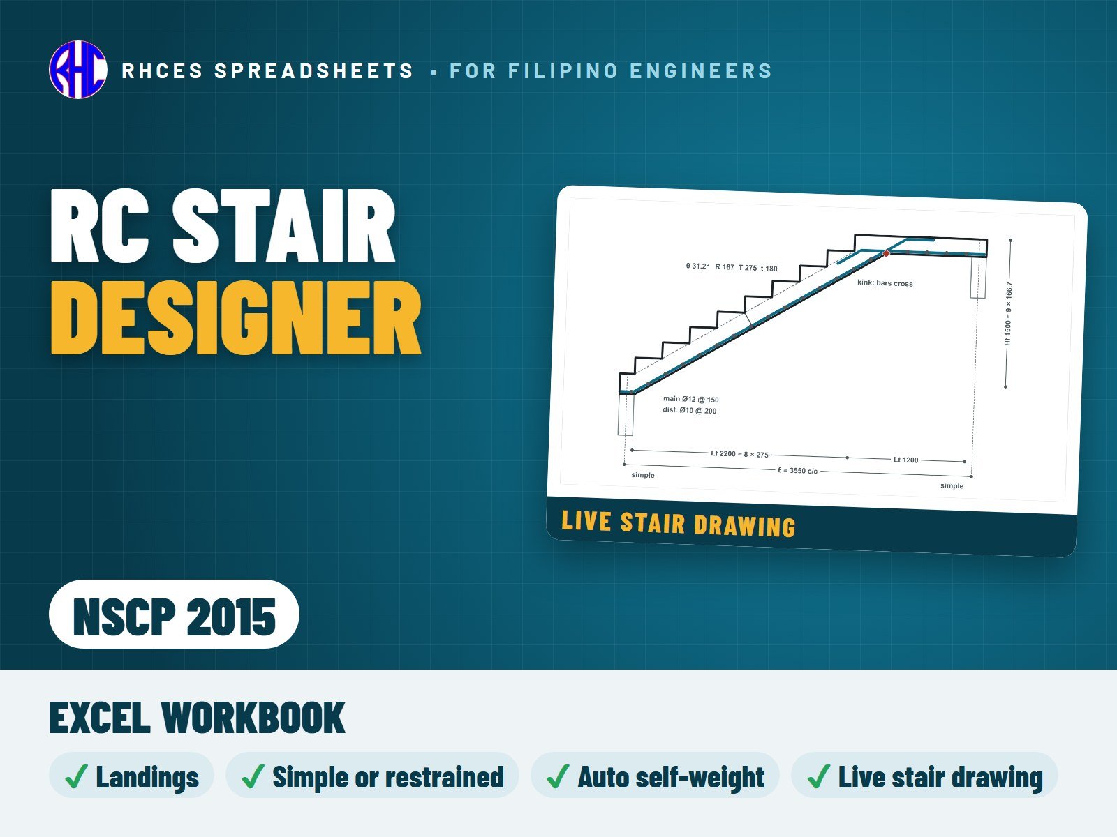
Preview of RC Stair Designer (NSCP 2015)
Structural

RC Stair Designer (NSCP 2015)

Design a reinforced-concrete waist-slab stair to NSCP 2015: a straight flight, or a flight with a landing at the bottom, at the top or at both ends, spanning along the flight between simple or restrained supports.

Enter the number of risers, the rise and tread, the landing lengths, the support widths, the materials, the bars and the loads (finishes, soffit, live load and an optional tread load). The sheet works out the self-weight of the waist and steps and the factored load, then the moments and shear: exact statics for simply supported flights, the NSCP 406.5 coefficients for restrained ends, or your own moments. It checks flexure with the effective depth perpendicular to the slope, ductility, minimum and distribution steel, bar spacing and crack control, cover, shear without stirrups, the minimum thickness for deflection, and the development and anchorage of the bars at the supports. It flags the re-entrant kink where a flight meets a landing above it and shows the crossing-bar detail, and gives editable riser, tread, 2R + T and headroom guidance lines.

A live drawing shows the steps, waist, landings, supports and every bar group. The check summary gives demand, capacity, ratio and PASS / FAIL for every line, with one overall result. Cross-checked against a published university stair example (within 0.3 %).

Not covered: cantilever, helical and free-standing stairs, precast stairs and flights with an intermediate support.

Every result is a visible Excel formula with printed NSCP 2015 clause and page references. Includes the Excel workbook. A worked A4 sample calculation can be previewed with View sample on the store page. One licence per engineer or office.

Excel · 4-page A4 calc sheet + live stair drawing
₱349.00View sample
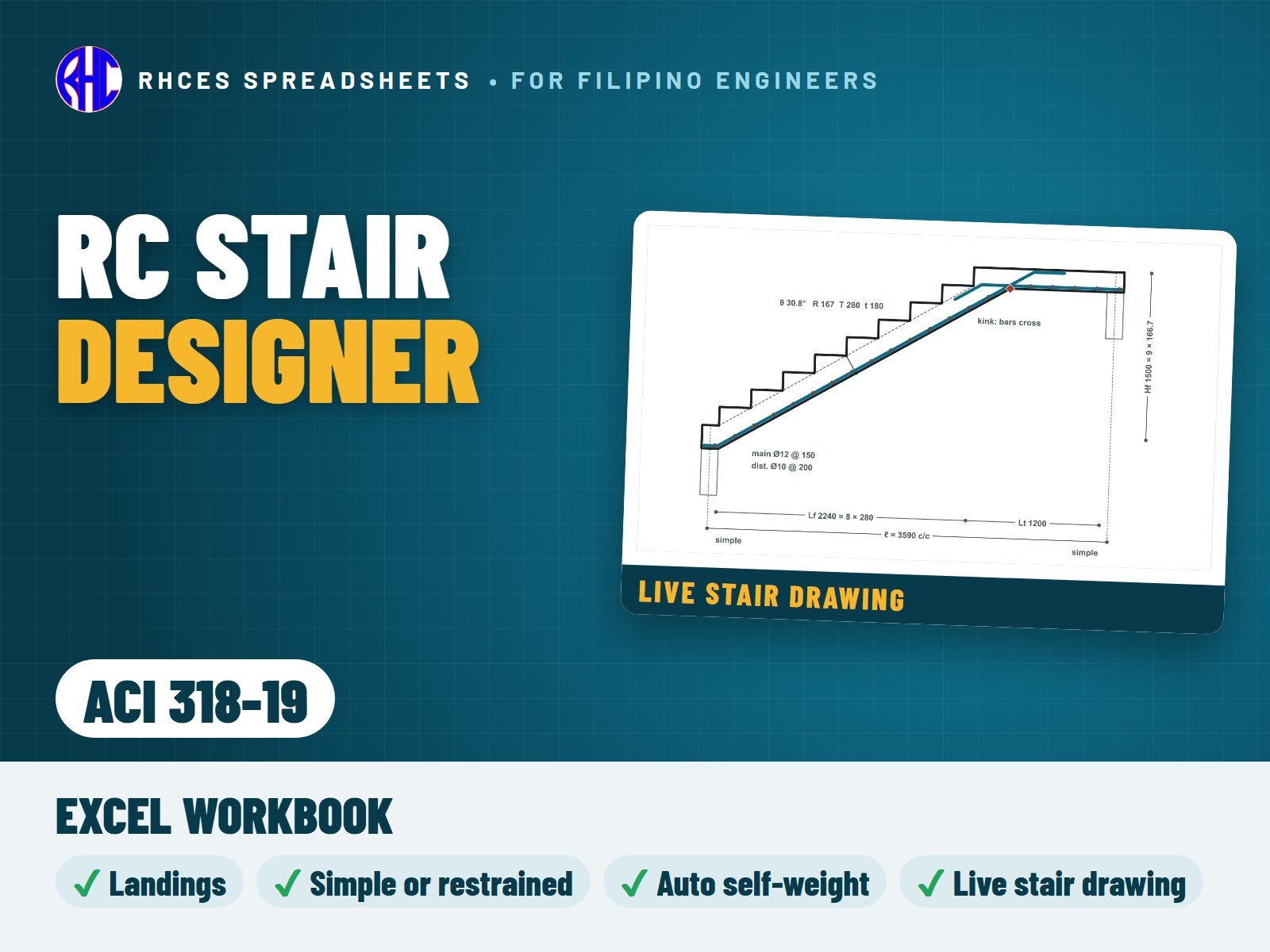
Preview of RC Stair Designer (ACI 318-19)
Structural

RC Stair Designer (ACI 318-19)

Design a reinforced-concrete waist-slab stair to ACI 318-19 (SI units): a straight flight, or a flight with a landing at the bottom, at the top or at both ends, spanning along the flight between simple or restrained supports.

Enter the number of risers, the rise and tread, the landing lengths, the support widths, the materials, the bars and the loads (finishes, soffit, live load and an optional tread load). The sheet works out the self-weight of the waist and steps and the factored load, then the moments and shear: exact statics for simply supported flights, the ACI 318 6.5 coefficients for restrained ends, or your own moments. It checks flexure with the effective depth perpendicular to the slope, ductility, minimum and distribution steel, bar spacing and crack control, cover, shear without stirrups by Table 22.5.5.1 (with the size effect), the minimum thickness for deflection, and the development and anchorage of the bars at the supports. It flags the re-entrant kink where a flight meets a landing above it and shows the crossing-bar detail, and gives editable riser, tread, 2R + T and headroom guidance lines.

A live drawing shows the steps, waist, landings, supports and every bar group. The check summary gives demand, capacity, ratio and PASS / FAIL for every line, with one overall result. Cross-checked against a published university stair example (within 0.3 %).

Not covered: cantilever, helical and free-standing stairs, precast stairs and flights with an intermediate support.

Every result is a visible Excel formula with ACI 318-19 section references. Includes the Excel workbook. A worked A4 sample calculation can be previewed with View sample on the store page. One licence per engineer or office. Looking for the Philippine code? See the NSCP 2015 edition.

Excel · 4-page A4 calc sheet + live stair drawing · SI units
₱349.00View sample
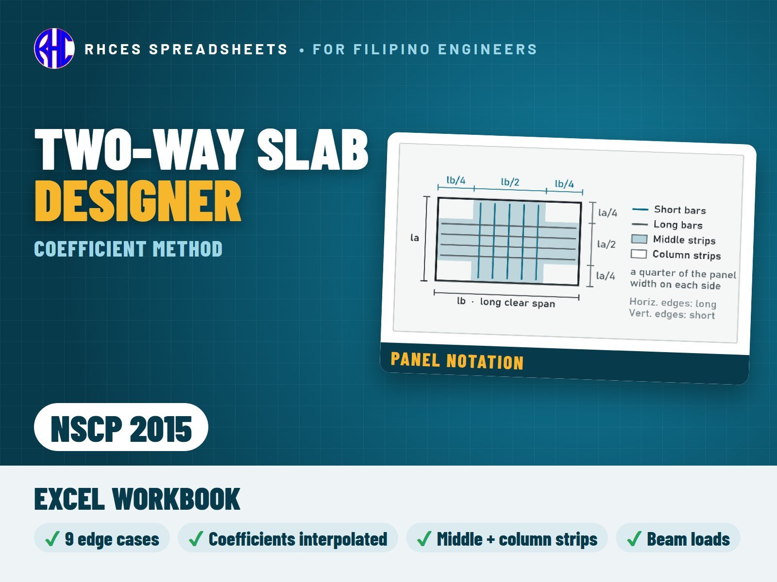
Preview of Two-Way Slab Designer (Coefficient Method, NSCP 2015)
Structural

Two-Way Slab Designer (Coefficient Method, NSCP 2015)

Design a two-way slab panel supported on beams or walls on all four edges, using the classic moment and shear coefficient method (ACI 318-63 Method 3, the tables used in Philippine design practice and textbooks), with the bars and checks to NSCP 2015.

Pick the edge condition from the 9 standard cases (with a sketch of each), enter the clear spans, thickness, loads and bars, and the sheet interpolates every coefficient for your span ratio. It works out the middle-strip negative and positive moments in both directions (dead and live load separately), the moments at discontinuous edges, and the column-strip values.

Checks each bar layer for strength and ductility, minimum steel, maximum spacing (2h / 450 mm), clear spacing, shear at both edges and minimum thickness (Table 408.3.1.2). It also gives the load carried to each supporting beam, ready for your beam design, and tells you to use the one-way slab method when la/lb is below 0.5.

The coefficient tables were cross-checked against three independent sources, including scans of the original ACI 318-63 tables. Every result is a visible Excel formula; prints as a clean A4 calculation sheet with the full coefficient tables.

Includes the Excel workbook. A worked A4 sample calculation can be previewed with View sample on the store page. One licence per engineer or office.

Excel · A4 calc sheet + full coefficient tables
₱349.00View sample
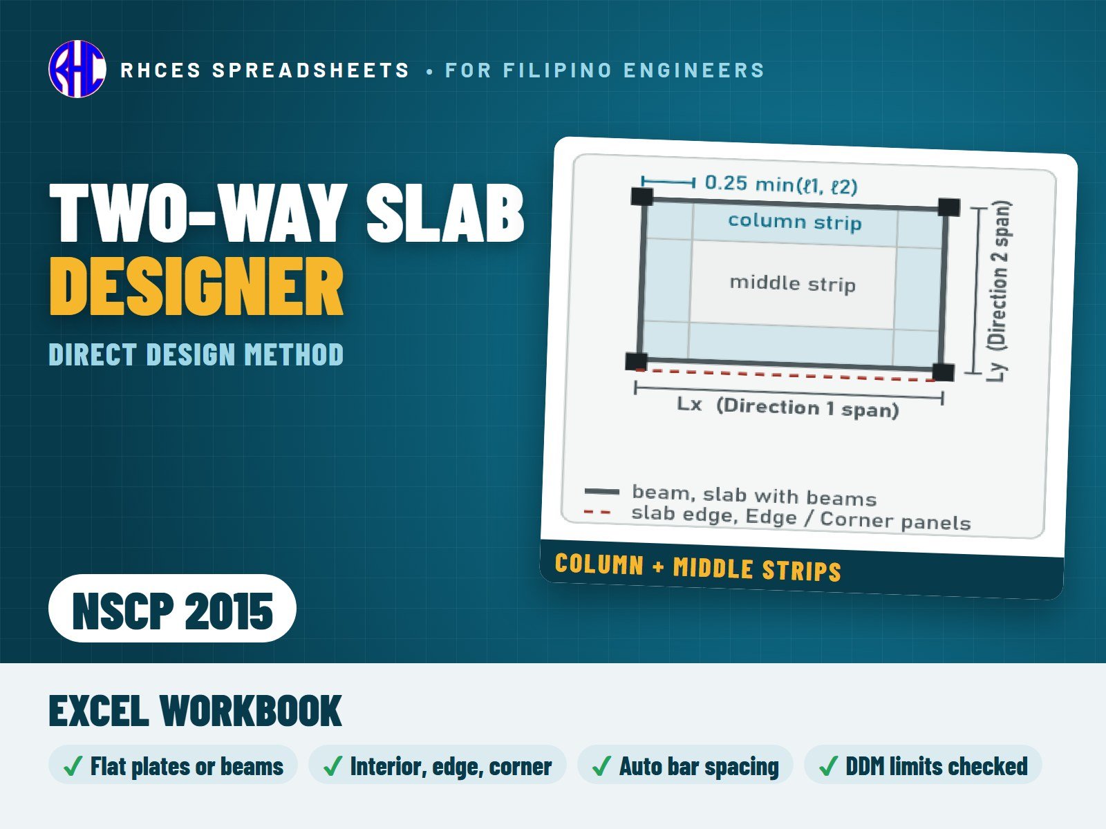
Preview of Two-Way Slab Designer (Direct Design Method, NSCP 2015)
Structural

Two-Way Slab Designer (Direct Design Method, NSCP 2015)

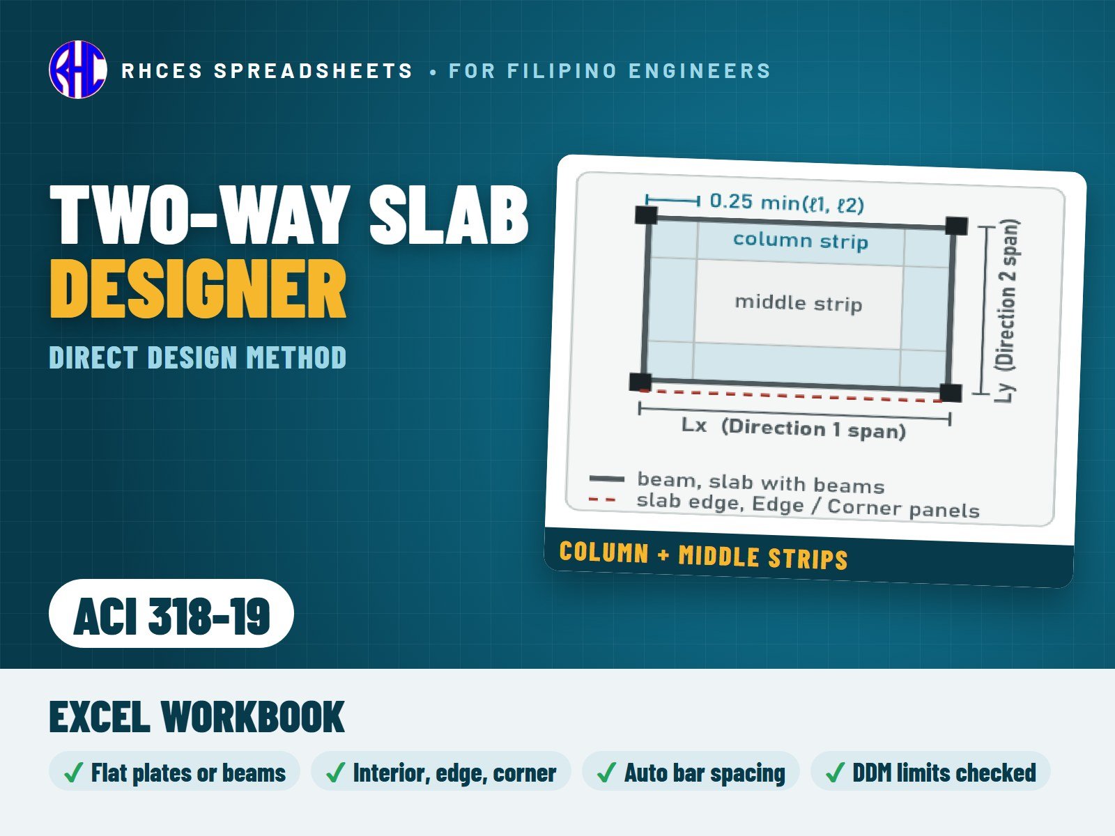
Design a two-way slab system with the Direct Design Method of NSCP 2015 Section 408.10: flat plates (with or without an edge beam) and slabs with beams between all supports, for interior, edge and corner panels, both directions side by side.

Checks the DDM limitations first, then works out the total static moment Mo, distributes it along the span with the code coefficients, and shares it between column strips, middle strips and beams using the code tables, with the beam stiffness ratio and torsional stiffness computed from your beam sizes.

Bars are sized automatically for every strip location ("Use Ø12 @ 200 mm") to satisfy the required steel, minimum steel and maximum spacing, or type your own spacing to check it. Also checks minimum thickness, one-way shear, and punching shear with moment transfer at interior and edge columns.

A design check summary shows every check with PASS / FAIL and one overall result. Every result is a visible Excel formula with NSCP 2015 clause references; prints as a clean A4 calculation with the DDM tables. Corner-column punching is not covered in this version.

Includes the Excel workbook. A worked A4 sample calculation can be previewed with View sample on the store page. One licence per engineer or office.

Excel · A4 calc sheet + DDM tables · auto bar spacing
₱399.00View sample
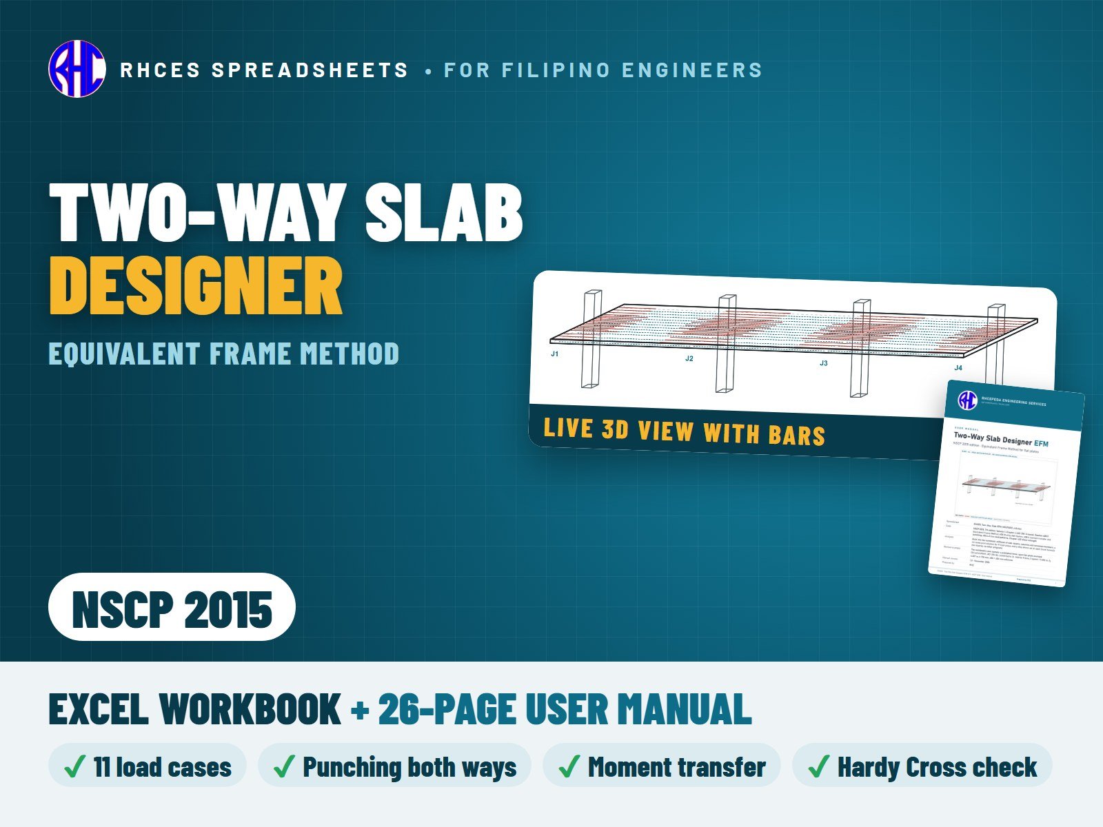
Preview of Two-Way Slab Designer (Equivalent Frame Method, NSCP 2015)
Structural

Two-Way Slab Designer (Equivalent Frame Method, NSCP 2015)

Analyse and design one equivalent frame of a flat-plate floor (a slab on columns, without beams or drop panels) by the Equivalent Frame Method of NSCP 2015 Section 408.11: the route for floors outside the Direct Design Method limits, such as fewer than three spans, unequal spans, long panels or heavy live loads. Type 1 to 6 spans with an optional cantilever at either end, an interior or an edge frame, the columns and storey heights above and below, the slab thickness, the loads and the bars (diameter and spacing) of every strip.

The sheet works out the stiffness of the slab-beams, the columns and the torsional members (the equivalent columns), solves the frame for the 11 load cases of 406.4.3 (full load and the live-load patterns) and takes the worst case at every section. It gives the moments at the critical sections with the optional 408.11.6.5 reduction, splits them into column and middle strips and checks your bars for flexure, minimum steel and spacing. It also checks moment transfer by flexure at the columns, punching shear in both directions with the unbalanced moments, one-way shear and the minimum thickness. A design check summary gives one result: SLAB ADEQUATE, REVISE SLAB or CHECK INPUTS. Live drawings follow the inputs: the frame elevation to scale, the bars in elevation, a plan and a 3D view, the moment and shear envelopes and the strip moments, with the maximum and minimum values. A Hand Check sheet repeats the full-load case by moment distribution (Hardy Cross).

Cross-checked against a published three-span flat-plate example. Every result is a visible Excel formula with printed NSCP 2015 clause references. Includes the Excel workbook and a 26-page user manual (A4 PDF) that takes the worked example step by step, with hand checks of the stiffnesses, moments, moment transfer and punching shear. A worked A4 sample calculation can be previewed with View sample on the store page. One licence per engineer or office.

Excel · A4 calc sheets + live frame elevation, plan, 3D view & M/V envelopes · 2 files incl. user manual
Includes 2 files: Excel workbook: Two-Way Slab Designer, Equivalent Frame Method, NSCP 2015 · User manual, A4 (26 pages)
₱449.00View sample
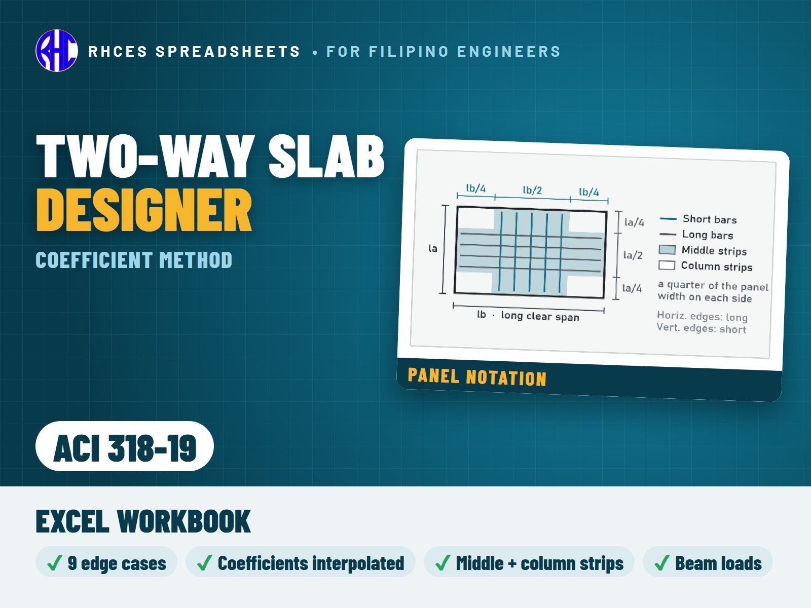
Preview of Two-Way Slab Designer (Coefficient Method, ACI 318-19)
Structural

Two-Way Slab Designer (Coefficient Method, ACI 318-19)

Design a two-way slab panel supported on beams or walls on all four edges with the classic moment and shear coefficient method (ACI 318-63 Method 3), with the bars and checks to ACI 318-19 (SI units).

Pick one of the 9 edge-condition cases (sketches included), enter spans, thickness, loads and bars, and the sheet interpolates every coefficient for your span ratio: middle-strip negative and positive moments both ways, discontinuous-edge moments and column-strip values.

Checks each bar layer for strength and the ACI 318-19 tension-controlled limit, minimum steel (0.0018 Ag), maximum spacing, clear spacing, shear at every edge with the ACI 318-19 size-effect formula, and minimum thickness. It also gives the load carried to each supporting beam. The coefficient tables were cross-checked against three independent sources, including scans of the original ACI 318-63 tables.
Every result is a visible Excel formula with ACI 318-19 clause references. Includes the Excel workbook. A worked A4 sample calculation can be previewed with View sample on the store page. One licence per engineer or office. Looking for the Philippine code? See the NSCP 2015 edition.

Excel · A4 calc sheet + full coefficient tables · SI units
₱349.00View sample
Preview of Two-Way Slab Designer (Direct Design Method, ACI 318-19)
Structural

Two-Way Slab Designer (Direct Design Method, ACI 318-19)

Design a two-way slab system with the Direct Design Method of ACI 318-19 Section 8.10 (SI units): flat plates (with or without an edge beam) and slabs with beams between all supports, for interior, edge and corner panels, both directions side by side.

Checks the DDM limitations, works out Mo, distributes it along the span and between column strips, middle strips and beams with the code tables (beam stiffness and torsion from your beam sizes), and sizes the bars automatically for every strip location, including the new ACI 318-19 minimum top steel at columns where punching stress is high (8.6.1.2).

Also checks minimum thickness, one-way shear and punching shear with the ACI 318-19 size effect and moment transfer at interior and edge columns (0.3 Mo at edge columns). Corner-column punching is not covered in this version.

Every result is a visible Excel formula with ACI 318-19 clause references. Includes the Excel workbook. A worked A4 sample calculation can be previewed with View sample on the store page. One licence per engineer or office. Looking for the Philippine code? See the NSCP 2015 edition.

Excel · A4 calc sheet + DDM tables · auto bar spacing · SI units
₱399.00View sample
Preview of Isolated Footing Designer (NSCP 2015)
Structural

Isolated Footing Designer (NSCP 2015)

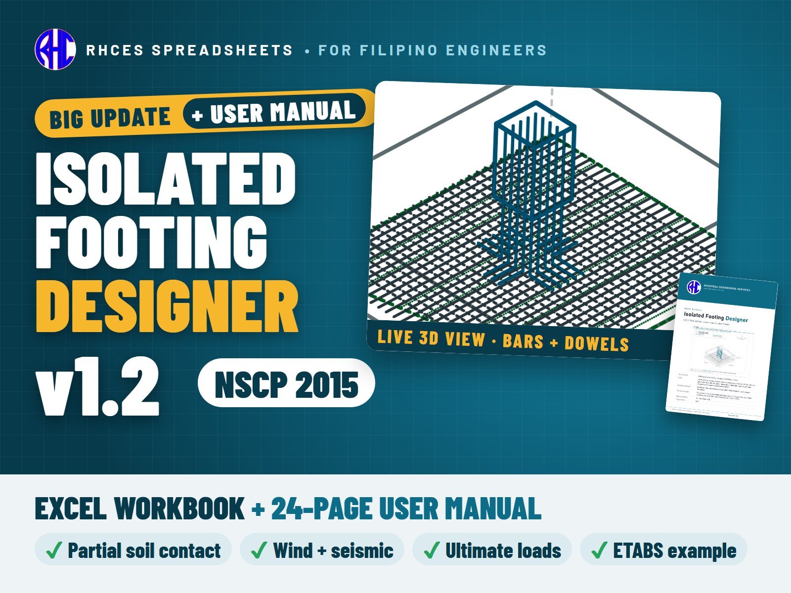
Design an isolated (spread) footing under a rectangular column to NSCP 2015, square or rectangular, from service loads to bars.

Enter the column, the dead and live axial loads (moments optional), the soil data and a trial footing. The sheet works out the net allowable soil pressure, the service pressure with moments and the full-contact (kern) check, and the factored soil pressure used for design.

Checks one-way shear in both directions, punching shear at d/2 including the shear from column moments, flexure at the column face both ways, minimum steel, the central-band rule for rectangular footings, bar spacing, development length of the bottom bars, column bearing, dowels and dowel development. Design aids suggest a square footing size and the bar spacing you need. A live footing plan shows the column, the critical sections, the steel band and where the load acts.

Every result is a visible Excel formula with NSCP 2015 clause references. Includes the Excel workbook and a 24-page user manual (A4 PDF) that takes a real ETABS 22.7 model step by step: the Joint Reactions of column C7 of a 3-storey residential building, the inputs, the load combinations, the results, partial contact and the Ultimate Loads mode. A worked A4 sample calculation can be previewed with View sample on the store page. One licence per engineer or office.

Version 1.1: column offset incl. edge and corner columns, live plan and elevation sketches with forces, live footing section.

Version 1.2: partial soil contact when e > L/6, wind and seismic load combinations with the NSCP one-third increase option, labelled load combinations, an Ultimate Loads input for the governing factored combination, and a live 3D view of the footing with rebar.

Excel · 5-page A4 calc sheet + live footing plan · v1.2 · 2 files incl. user manual
Includes 2 files: Excel workbook: Isolated Footing Designer, NSCP 2015 · User manual, A4 (24 pages)
₱449.00View sample
Preview of Isolated Footing Designer (ACI 318-19)
Structural

Isolated Footing Designer (ACI 318-19)

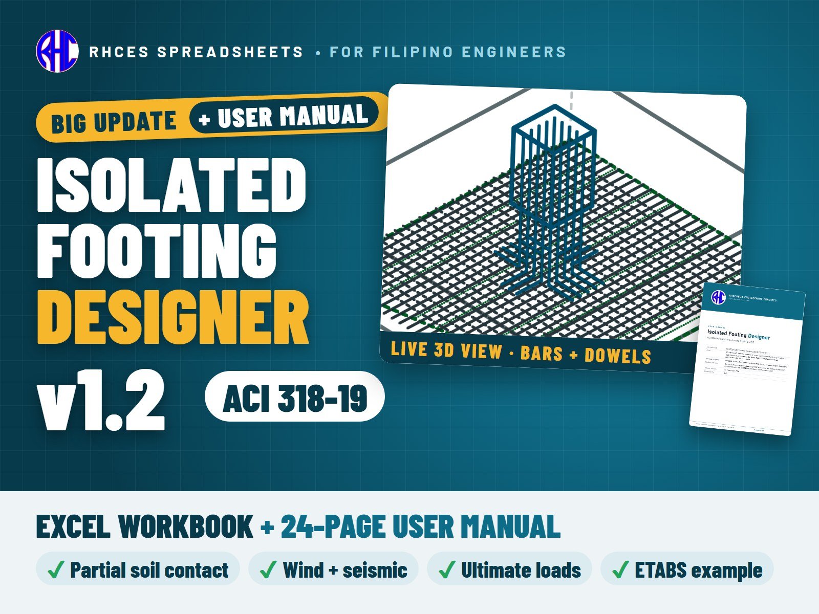
Design an isolated (spread) footing under a rectangular column to ACI 318-19 (SI units), square or rectangular, from service loads to bars.

Enter the column, the dead and live axial loads (moments optional), the soil data and a trial footing. The sheet works out the net allowable soil pressure, the service pressure with moments and the full-contact (kern) check, and the factored soil pressure used for design.

Checks one-way shear in both directions, punching shear at d/2 including the shear from column moments, flexure at the column face both ways, minimum steel, the central-band rule for rectangular footings, bar spacing, development length of the bottom bars, column bearing, dowels and dowel development. Design aids suggest a square footing size and the bar spacing you need. A live footing plan shows the column, the critical sections, the steel band and where the load acts.

ACI 318-19 specifics: one-way shear with the Table 22.5.5.1 formula, a switch for the size-effect factor (13.2.6.2 lets you neglect it for footings), the 8.6.1.2 minimum steel near the column, minimum steel 0.0018 Ag and the εty + 0.003 ductility limit.

Every result is a visible Excel formula with ACI 318-19 clause references. Includes the Excel workbook and a 24-page user manual (A4 PDF) that takes a real ETABS 22.7 model step by step: the Joint Reactions of column C7 of a 3-storey residential building, the inputs, the load combinations, the results, partial contact and the Ultimate Loads mode. A worked A4 sample calculation can be previewed with View sample on the store page. One licence per engineer or office. Looking for the Philippine code? See the NSCP 2015 edition.

Version 1.1: column offset incl. edge and corner columns, live plan and elevation sketches with forces, live footing section.

Version 1.2: partial soil contact when e > L/6, wind and seismic ASCE 7 / IBC load combinations with an optional allowable increase (%), labelled load combinations, an Ultimate Loads input for the governing factored combination, and a live 3D view of the footing with rebar.

Excel · 5-page A4 calc sheet + live footing plan · SI units · v1.2 · 2 files incl. user manual
Includes 2 files: Excel workbook: Isolated Footing Designer, ACI 318-19 · User manual, A4 (24 pages)
₱449.00View sample
Preview of Combined Footing Designer (NSCP 2015)
Structural

Combined Footing Designer (NSCP 2015)

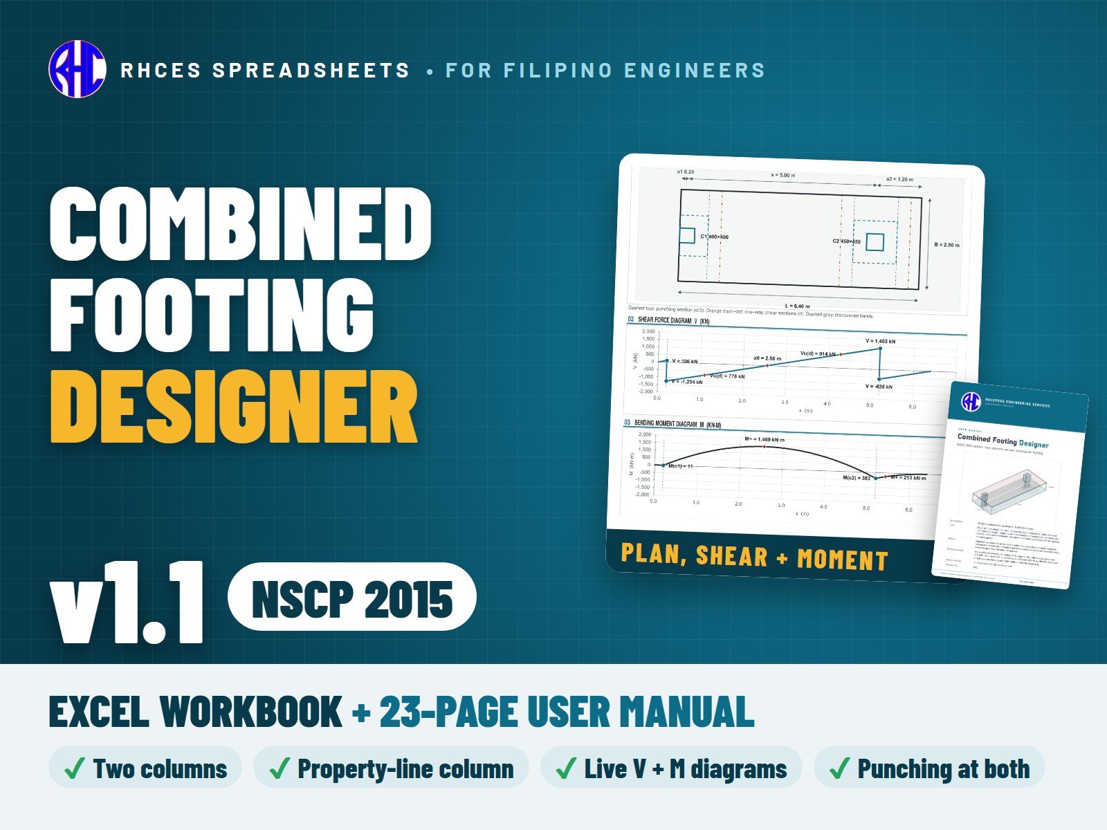
Design a rectangular combined footing carrying two columns to NSCP 2015, including an exterior column right at the property line.

The sheet sizes the footing length so the soil pressure is uniform (load resultant at the centre), or checks a length you enter with the trapezoidal pressure and the kern check. The footing is then designed as a beam along its length, with live shear-force and bending-moment diagrams: the largest negative moment between the columns sets the top bars, the moments at the column faces set the bottom bars.

Checks one-way shear at d from the column faces, punching at both columns (a three-sided edge section for a column at the property line), flexure and ductility of the top and bottom bars, transverse bands under each column, minimum steel, spacing, development length (top-bar factor applied), column bearing and dowels. A live plan drawing shows the columns, critical sections and transverse bands. Column moments are carried into the soil pressure, the beam analysis and the punching check (moment transfer).

Every result is a visible Excel formula with NSCP 2015 clause references. Includes the Excel workbook and a 23-page user manual (A4 PDF) that takes the worked example step by step, with hand checks. A worked A4 sample calculation can be previewed with View sample on the store page. One licence per engineer or office.

Version 1.1: service moments at each column, punching shear with moment transfer, an Ultimate Loads input for the governing factored combination, wind and seismic load combinations with the NSCP one-third increase option, a live plan and elevation drawn to scale, and a live 3D view of the footing with rebar.

Excel · A4 calc sheet + live plan, shear & moment diagrams · 2 files incl. user manual
Includes 2 files: Excel workbook: Combined Footing Designer, NSCP 2015 · User manual, A4 (23 pages)
₱449.00View sample
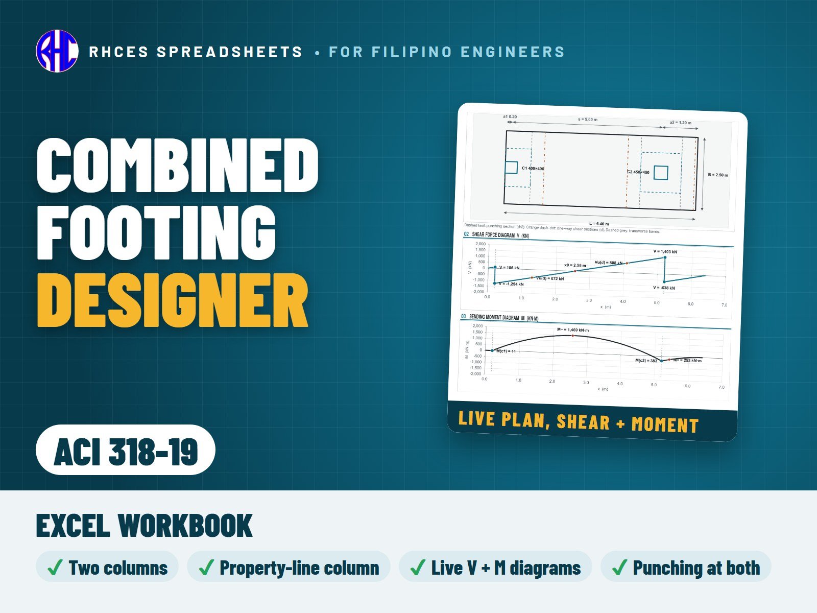
Preview of Combined Footing Designer (ACI 318-19)
Structural

Combined Footing Designer (ACI 318-19)

Design a rectangular combined footing carrying two columns to ACI 318-19 (SI units), including an exterior column right at the property line.

The sheet sizes the footing length so the soil pressure is uniform (load resultant at the centre), or checks a length you enter with the trapezoidal pressure and the kern check. The footing is then designed as a beam along its length, with live shear-force and bending-moment diagrams: the largest negative moment between the columns sets the top bars, the moments at the column faces set the bottom bars.

Checks one-way shear at d from the column faces, punching at both columns (a three-sided edge section for a column at the property line), flexure and ductility of the top and bottom bars, transverse bands under each column, minimum steel, spacing, development length (top-bar factor applied), column bearing and dowels. A live plan drawing shows the columns, critical sections and transverse bands. Gravity loads; moment transfer at the columns is not included in this version.

ACI 318-19 specifics: one-way shear with the Table 22.5.5.1 formula, a switch for the size-effect factor (13.2.6.2 lets you neglect it for footings), minimum steel 0.0018 Ag and the εty + 0.003 ductility limit.

Every result is a visible Excel formula with ACI 318-19 clause references. Includes the Excel workbook. A worked A4 sample calculation can be previewed with View sample on the store page. One licence per engineer or office. Looking for the Philippine code? See the NSCP 2015 edition.

Excel · A4 calc sheet + live plan, shear & moment diagrams · SI units
₱449.00View sample
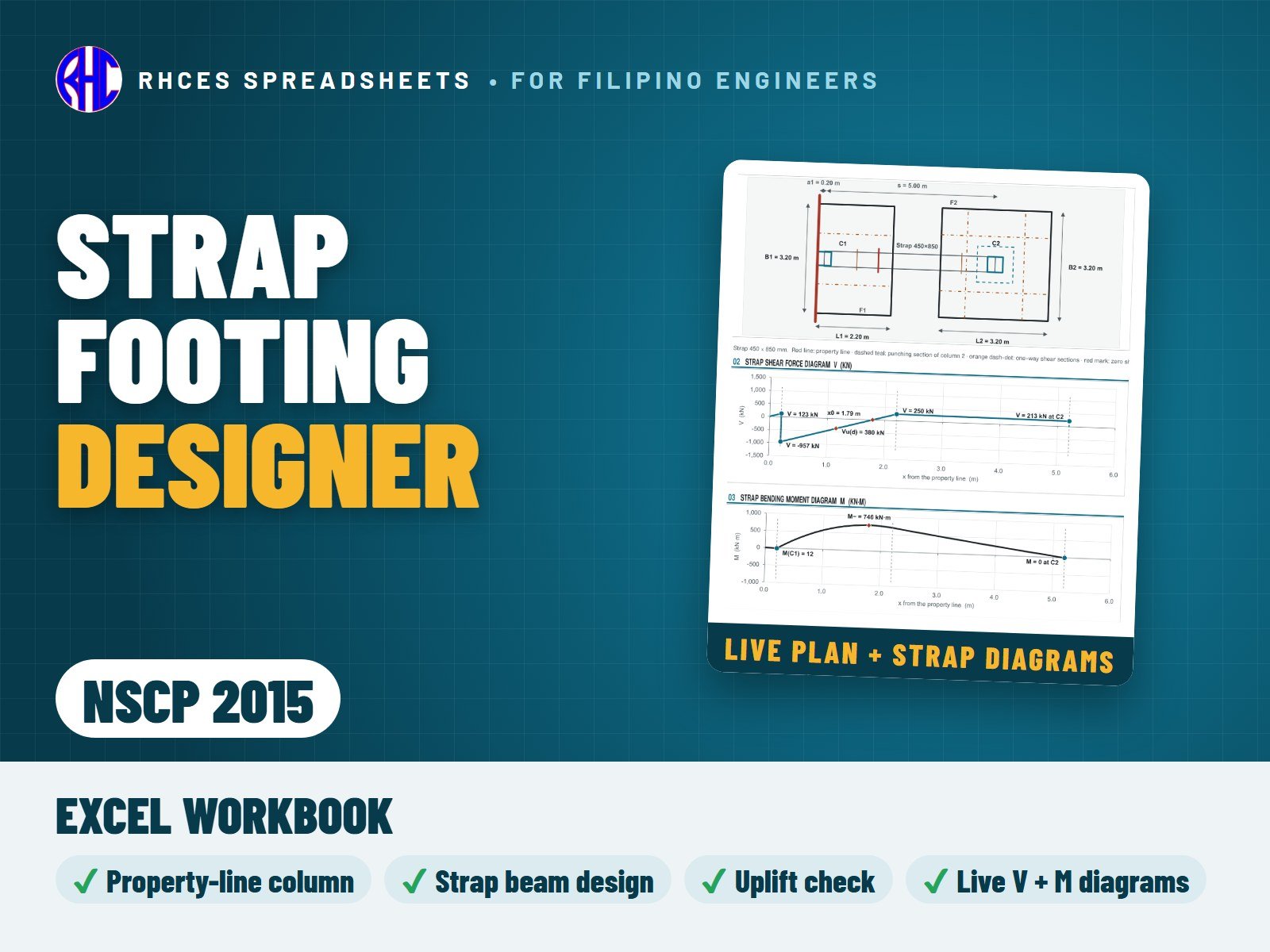
Preview of Strap Footing Designer (NSCP 2015)
Structural

Strap Footing Designer (NSCP 2015)

Design a strap (cantilever) footing to NSCP 2015: an exterior column at the property line on its own footing, tied by a strap beam to an interior column on a concentric footing, so the soil pressure stays uniform under both.

The sheet solves the statics for the two footing reactions (strap self-weight optional), sizes the footings from the allowable soil pressure, and lets you design the interior footing for the full column load (default, conservative) or the reduced reaction. It checks uplift on the interior footing.

Strap beam: live shear and bending-moment diagrams, top steel for the maximum moment, minimum bottom steel and any sagging, ductility, stirrups (Vc, Vs, maximum spacing, minimum shear steel, section limit) and anchorage of the top bars at the property-line end. Exterior footing: designed across as cantilevers from the strap faces, with one-way shear, flexure, steel both ways, spacing and development. Interior footing: punching, one-way shear and flexure both ways, central band, development. Column bearing and dowels for both columns. A true-scale plan shows the property line, both footings, the strap and the critical sections. The strap is assumed not to bear on the soil (the Read Me gives the detailing note). Gravity loads.

Every result is a visible Excel formula with NSCP 2015 clause references. Includes the Excel workbook. A worked A4 sample calculation can be previewed with View sample on the store page. One licence per engineer or office.

Excel · A4 calc sheet + live plan, strap shear & moment diagrams
₱449.00View sample
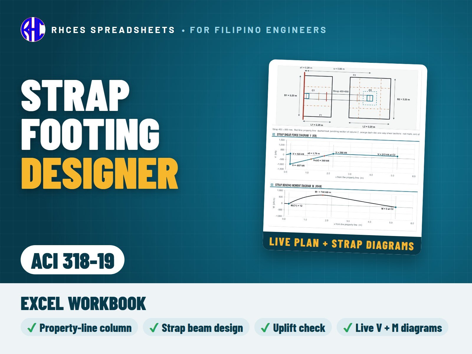
Preview of Strap Footing Designer (ACI 318-19)
Structural

Strap Footing Designer (ACI 318-19)

Design a strap (cantilever) footing to ACI 318-19 (SI units): an exterior column at the property line on its own footing, tied by a strap beam to an interior column on a concentric footing, so the soil pressure stays uniform under both.

The sheet solves the statics for the two footing reactions (strap self-weight optional), sizes the footings from the allowable soil pressure, and lets you design the interior footing for the full column load (default, conservative) or the reduced reaction. It checks uplift on the interior footing.

Strap beam: live shear and bending-moment diagrams, top steel for the maximum moment, minimum bottom steel and any sagging, ductility, stirrups (Vc by Table 22.5.5.1, Vs, maximum spacing, minimum shear steel, section limit) and anchorage of the top bars at the property-line end. Exterior footing: designed across as cantilevers from the strap faces, with one-way shear, flexure, steel both ways, spacing and development. Interior footing: punching (with the optional size effect), one-way shear and flexure both ways, central band, the flexure-driven punching steel of 8.6.1.2, development. Column bearing and dowels for both columns. A true-scale plan shows the property line, both footings, the strap and the critical sections. Gravity loads.

Every result is a visible Excel formula with ACI 318-19 section references. Includes the Excel workbook. A worked A4 sample calculation can be previewed with View sample on the store page. One licence per engineer or office. Looking for the Philippine code? See the NSCP 2015 edition.

Excel · A4 calc sheet + live plan, strap shear & moment diagrams · SI units
₱449.00View sample
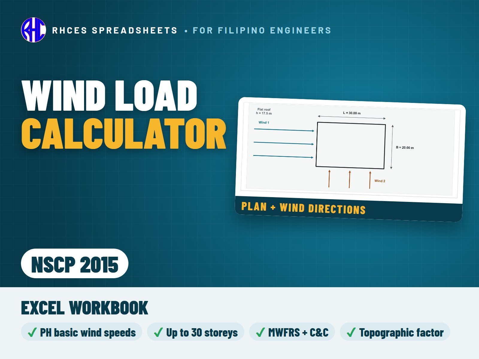
Preview of Wind Load Calculator (NSCP 2015)
Structural

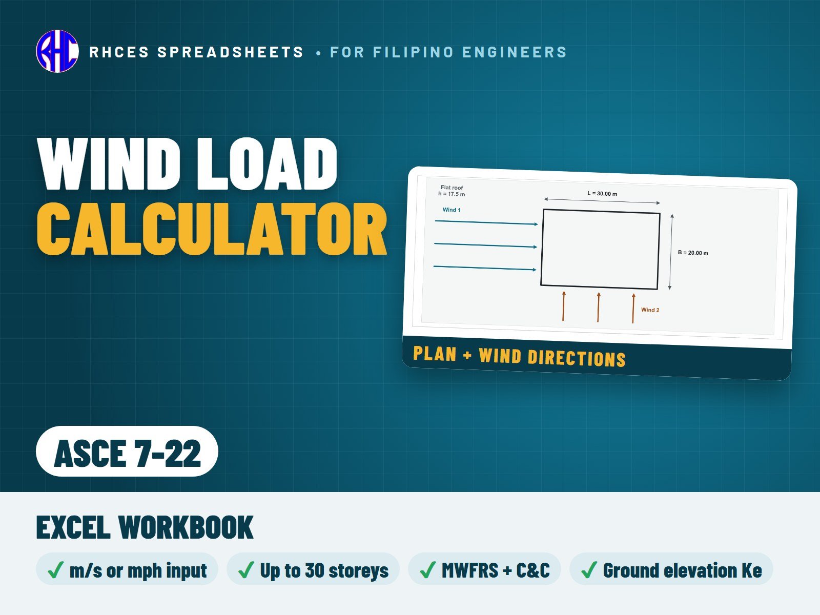
Wind Load Calculator (NSCP 2015)

Calculate wind loads on buildings to NSCP 2015 Section 207, with the Philippine basic wind speeds (km/h) and the NSCP occupancy categories.

Covers enclosed and partially enclosed rigid buildings with flat, gable, hip or monoslope roofs. Enter the plan size, storey heights (up to 30 storeys), roof shape and slope, exposure and the basic wind speed; the sheet works out Kz at every level, the topographic factor (2-D ridge, 2-D escarpment or 3-D hill, optional), qz and qh, the gust factor with a rigid/flexible check, and the external pressure coefficients for walls and roof by interpolation.

Main wind-force-resisting system (directional procedure): design pressures for wind in both principal directions and both internal-pressure signs, storey forces, storey shears and overturning moments, base shear and base moment, and the minimum design wind load check. Components and cladding (buildings up to 18 m): wall and roof zone pressures by effective wind area, with the zone width and the minimum pressure. Live charts show the plan with the wind directions, the pressure profile, storey forces, shears and moments.

Every coefficient was taken from the printed NSCP 2015 and every result is a visible Excel formula with NSCP clause references. Includes the Excel workbook. A worked A4 sample calculation can be previewed with View sample on the store page. One licence per engineer or office.

Excel · A4 calc sheets + storey forces, C&C and live charts
₱349.00View sample
Preview of Wind Load Calculator (ASCE 7-22)
Structural

Wind Load Calculator (ASCE 7-22)

Calculate wind loads on buildings to ASCE 7-22 in SI units (wind speed in m/s, or type it in mph), including the ground elevation factor Ke and the ASCE 7-22 components-and-cladding zones.

Covers enclosed and partially enclosed rigid buildings with flat, gable, hip or monoslope roofs. Enter the plan size, storey heights (up to 30 storeys), roof shape and slope, exposure and the basic wind speed; the sheet works out Kz at every level, the topographic factor (2-D ridge, 2-D escarpment or 3-D hill, optional), qz and qh, the gust factor with a rigid/flexible check, and the external pressure coefficients for walls and roof by interpolation.

Main wind-force-resisting system (directional procedure): design pressures for wind in both principal directions and both internal-pressure signs, storey forces, storey shears and overturning moments, base shear and base moment, and the minimum design wind load check. Components and cladding (buildings up to 18 m): wall and roof zone pressures by effective wind area, with the zone width and the minimum pressure. Live charts show the plan with the wind directions, the pressure profile, storey forces, shears and moments.

Every result is a visible Excel formula with ASCE 7-22 section references; the Read Me lists the scope and limits. Includes the Excel workbook. A worked A4 sample calculation can be previewed with View sample on the store page. One licence per engineer or office. Looking for the Philippine code? See the NSCP 2015 edition.

Excel · A4 calc sheets + storey forces, C&C and live charts · SI (mph input)
₱349.00View sample
Preview of Seismic Load Calculator (NSCP 2015)
Structural

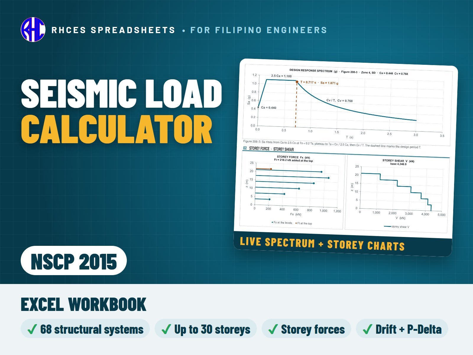
Seismic Load Calculator (NSCP 2015)

Calculate earthquake loads on buildings to NSCP 2015 Section 208 (static lateral force procedure), with the Philippine seismic zones, soil profile types and near-source factors.

Select the structural system from all 68 lines of Tables 208-11A to 208-11D (R, Ω0 and the height limits for Zones 2 and 4 are filled in), then enter the zone, soil profile, seismic source type and distance, occupancy category and the storey heights and weights (up to 30 storeys); the sheet works out Ca, Cv, Na and Nv, the fundamental period by Method A (or Method B within its cap) and the design base shear with the limits of Eq. 208-8 to 208-11, or the simplified procedure where it is permitted.

Vertical distribution: Ft at the top, storey forces, storey shears and overturning moments. Also the redundancy factor ρ, Eh, Ev and Em = Ω0 Eh, and storey drift and P-Delta checks from the elastic displacements you enter (ΔM = 0.7 R ΔS). The checks flag a system that is not permitted or above its height limit, when the dynamic procedure is required, and soil profile SF. Live charts show the design response spectrum, storey forces, shears, moments and drift.

Every coefficient was taken from the printed NSCP 2015 and every result is a visible Excel formula with NSCP clause references. Includes the Excel workbook. A worked A4 sample calculation can be previewed with View sample on the store page. One licence per engineer or office.

Excel · A4 calc sheets + storey forces, drift/P-Delta and live charts
₱349.00View sample
Preview of Seismic Load Calculator (ASCE 7-22)
Structural

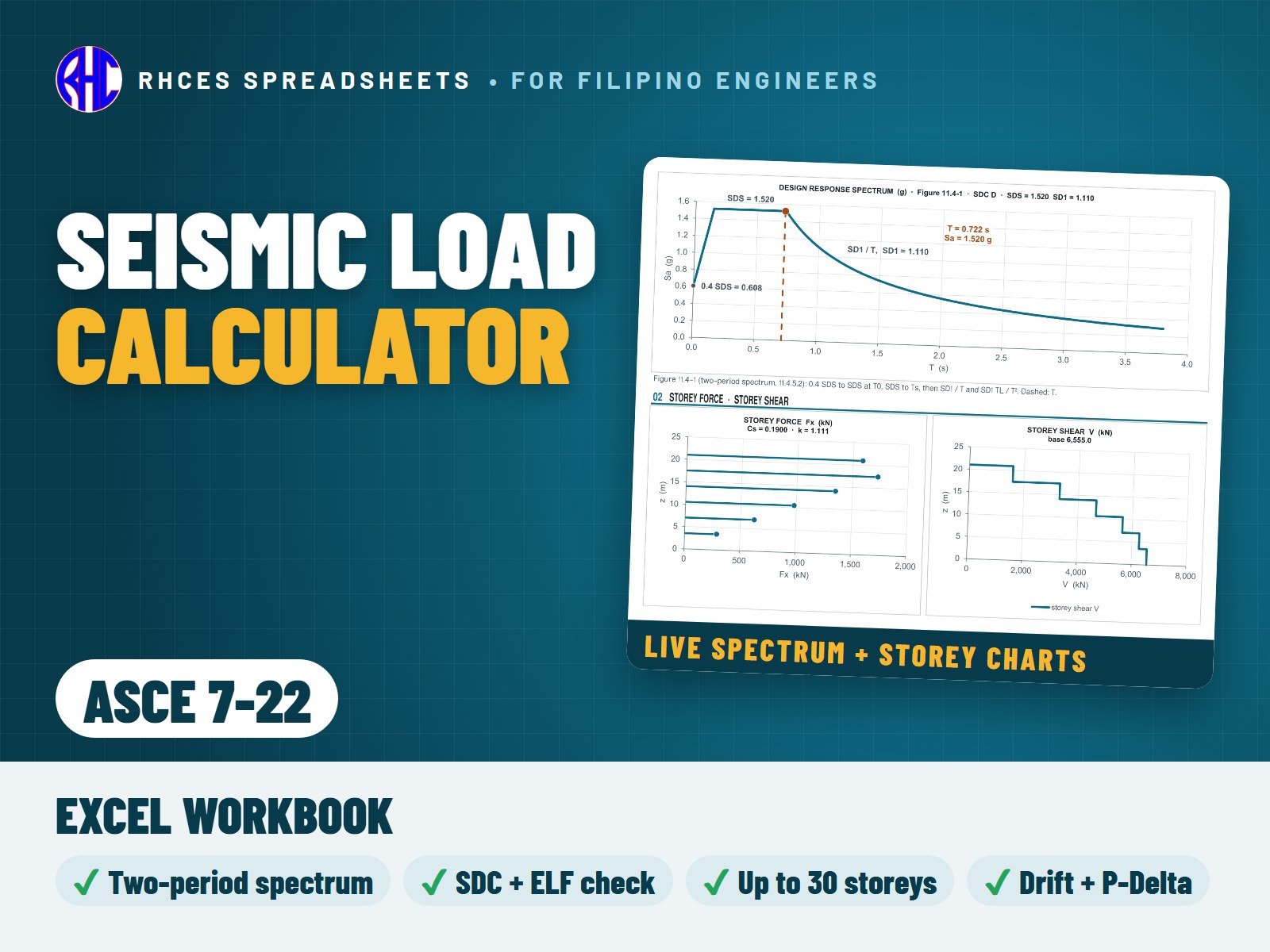
Seismic Load Calculator (ASCE 7-22)

Calculate earthquake loads on buildings to ASCE 7-22 Chapters 11 and 12 (Equivalent Lateral Force procedure) in SI units, with the new site classes BC, CD and DE and the two-period design spectrum.

Enter SDS, SD1, S1 and TL from the USGS ASCE 7-22 Hazard Tool, the risk category and site class, and select the structural system from Table 12.2-1 (R, Ω0, Cd and the height limits are filled in, or type your own); the sheet works out the Seismic Design Category, checks whether the ELF procedure is permitted (Table 12.6-1), the approximate period with the Cu cap, Cs with its upper and lower limits, and the base shear V = Cs W.

Vertical distribution with the exponent k for up to 30 storeys: storey forces, shears and overturning moments. Also ρ, Eh, Ev and Em, and storey drift (δx = Cd δxe / Ie against Table 12.12-1) and P-Delta stability from the elastic displacements you enter. Live charts show the design spectrum, storey forces, shears, moments and drift.

Every result is a visible Excel formula with ASCE 7-22 section references; the Read Me lists the scope, the limits and the values to confirm against your copy of the standard. Includes the Excel workbook. A worked A4 sample calculation can be previewed with View sample on the store page. One licence per engineer or office. Looking for the Philippine code? See the NSCP 2015 edition.

Excel · A4 calc sheets + storey forces, drift/P-Delta and live charts · SI units
₱349.00View sample
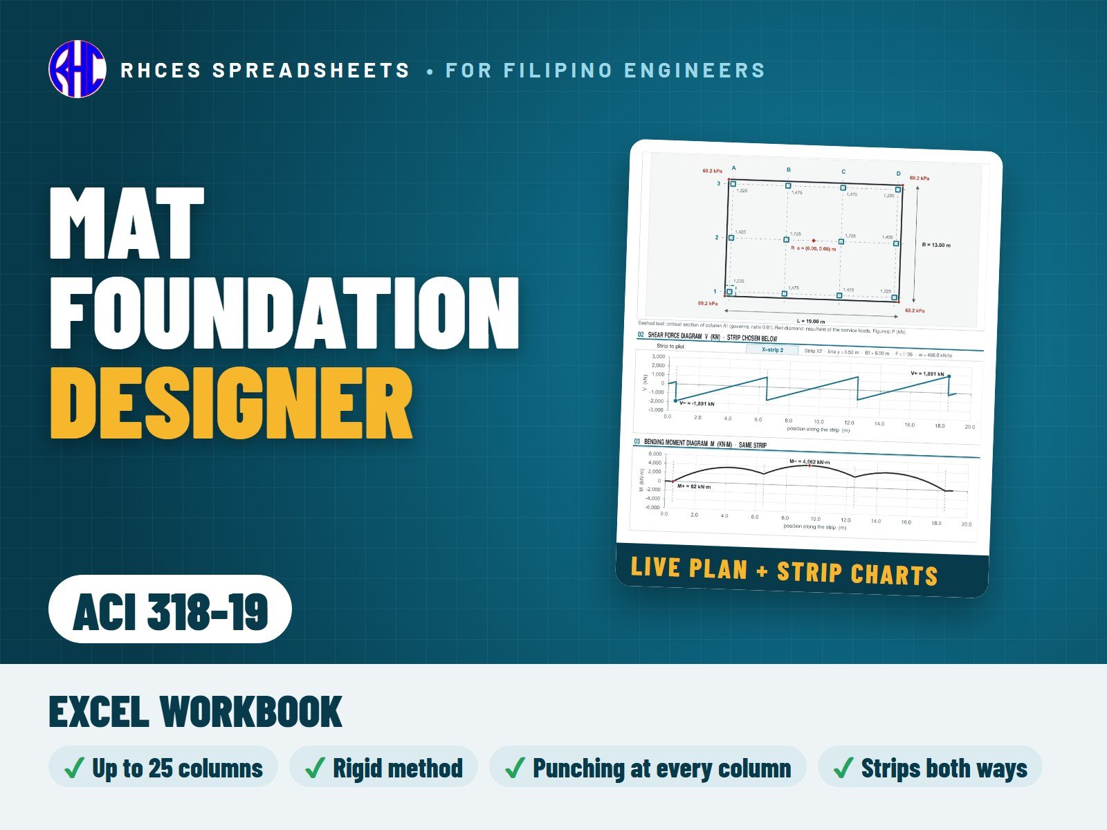
Preview of Mat Foundation Designer (NSCP 2015)
Structural

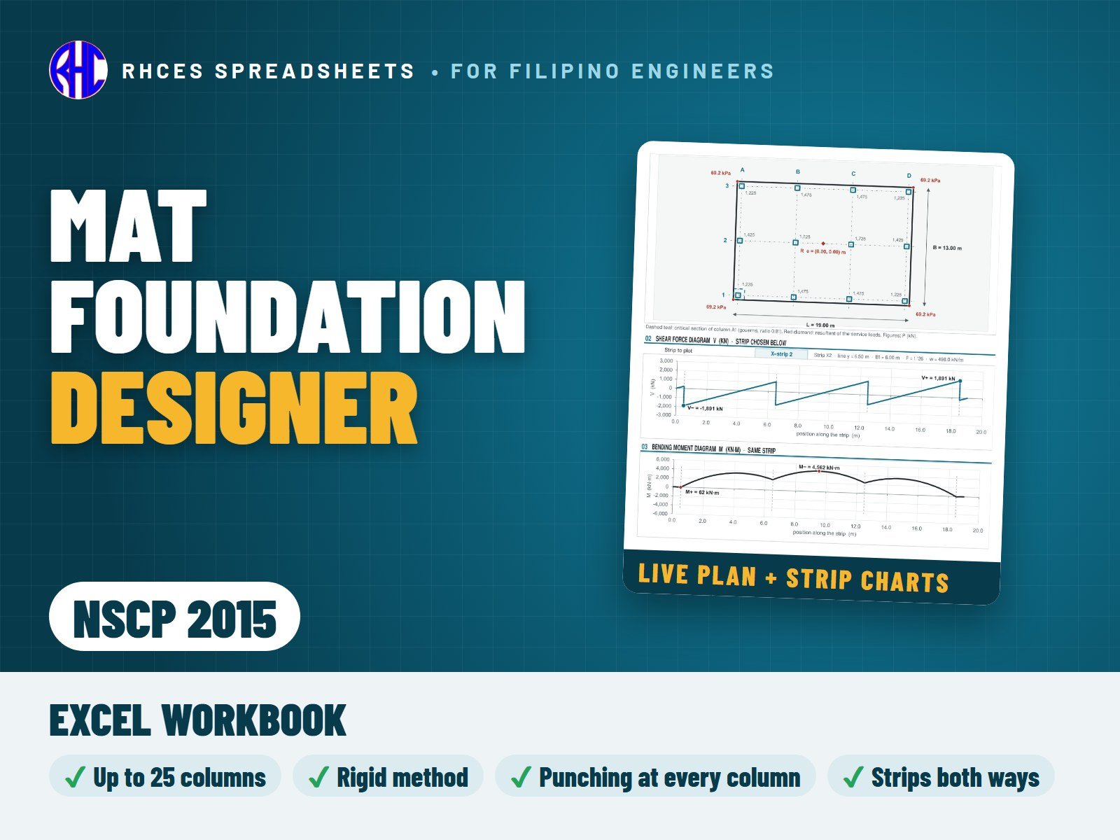
Mat Foundation Designer (NSCP 2015)

Design a rectangular mat (raft) foundation of uniform thickness under a regular grid of columns (2 to 5 column lines each way, up to 25 columns) by the conventional rigid method (ACI 336.2R; Das; Bowles) to NSCP 2015: rigidity check, soil pressure under service and factored column loads from the resultant, punching shear at every column (interior, edge and corner sections, cut by the mat edge when the overhang is short), the strip method in both directions with the load / reaction adjustment, shear and moment of every strip as live tables and charts, one-way shear in the strips, top and bottom reinforcement both ways per metre, spacing, development and column bearing.

Enter the mat size and thickness, the column grid and loads, the soil pressure and the materials; the sheet draws the plan with the strips and reports every check with PASS / FAIL and one overall result.

Every result is a visible Excel formula with NSCP 2015 clause references. Includes the Excel workbook. A worked A4 sample calculation can be previewed with View sample on the store page. One licence per engineer or office.

Excel · A4 calc sheets + live plan, strip shear & moment charts
₱499.00View sample
Preview of Mat Foundation Designer (ACI 318-19)
Structural

Mat Foundation Designer (ACI 318-19)

Design a rectangular mat (raft) foundation of uniform thickness under a regular grid of columns (2 to 5 column lines each way, up to 25 columns) by the conventional rigid method (ACI 336.2R; Das; Bowles) to ACI 318-19 (SI units): rigidity check, soil pressure under service and factored column loads from the resultant, punching shear at every column (interior, edge and corner sections, cut by the mat edge when the overhang is short) with the flexure-driven punching steel of 8.6.1.2, the strip method in both directions with the load / reaction adjustment, shear and moment of every strip as live tables and charts, one-way shear in the strips, top and bottom reinforcement both ways per metre, spacing, development and column bearing.

Enter the mat size and thickness, the column grid and loads, the soil pressure and the materials; the sheet draws the plan with the strips and reports every check with PASS / FAIL and one overall result.

Every result is a visible Excel formula with ACI 318-19 section references. Includes the Excel workbook. A worked A4 sample calculation can be previewed with View sample on the store page. One licence per engineer or office. Looking for the Philippine code? See the NSCP 2015 edition.

Excel · A4 calc sheets + live plan, strip shear & moment charts · SI units
₱499.00View sample
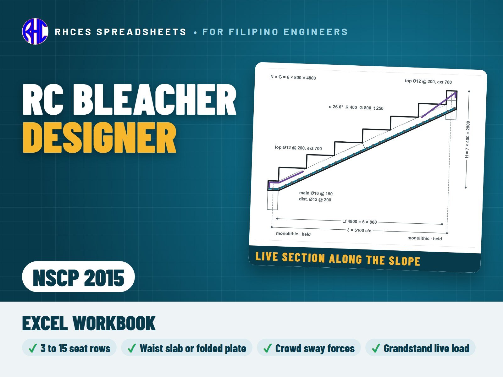
Preview of RC Bleacher Designer (NSCP 2015)
Structural

RC Bleacher Designer (NSCP 2015)

Design one cast-in-place reinforced concrete bleacher (grandstand seating) whose stepped slab spans along the slope between a bottom and a top support, like a stair flight, to NSCP 2015. Designed per 1 m strip along the rows, 3 to 15 seat rows, as a waist slab (flat inclined soffit with solid or hollow steps on top) or a folded plate (sawtooth treads and risers). Optional walkways at the bottom and top; each support is a monolithic beam, a held bearing on a ledge or wall, or a sliding bearing.

Loads: self-weight, seats and finishes, the NSCP 2015 Table 205-1 grandstand live load (4.8 kPa), crowd sway forces from Table 205-2 (350 N/m along and 145 N/m across the seats) and an optional guard on the top edge. Simple-span statics on the horizontal projection, with a check that one support slides or the ends are symmetric (otherwise the slab arches and the sheet asks for a frame analysis). Moments and shear from your own frame analysis can be typed in; they only ever raise the demand.

Checks: flexure at mid-span, at the folds (riser moment plus axial force) and at monolithic supports; ductility, minimum and shrinkage steel, bar spacing, crack control, cover and concrete strength for the exposure class; one-way shear; minimum thickness and the calculated live-load and long-term deflections; crowd vibration (natural frequency against the crowd limit and the Allen rhythmic-crowd check, reported as CHECK); end-support reactions, bearing and sway at held bearings; development of the bars at the supports, at the waist kink and across the folds, top-bar extension and embedment, hanging risers and laps.

Live drawings show the bleacher in section along the slope with its bars, the fold detail and the moment and shear diagrams; the 46-line summary reports demand, capacity, ratio and PASS / FAIL / CHECK with one overall result. Not covered: precast, steel or timber seating, telescopic stands, seats spanning across the rows between raker beams, cantilevered tiers, intermediate supports, and the seismic and wind design of the stand, its beams, rakers, columns and footings. The Read Me lists the items worth confirming.

Every result is a visible Excel formula, with printed NSCP 2015 clause and page references for the code items. Includes the Excel workbook. A worked A4 sample calculation can be previewed with View sample on the store page. One licence per engineer or office.

Excel · A4 calc sheets + live section along the slope, fold detail, moment & shear diagrams
₱449.00View sample
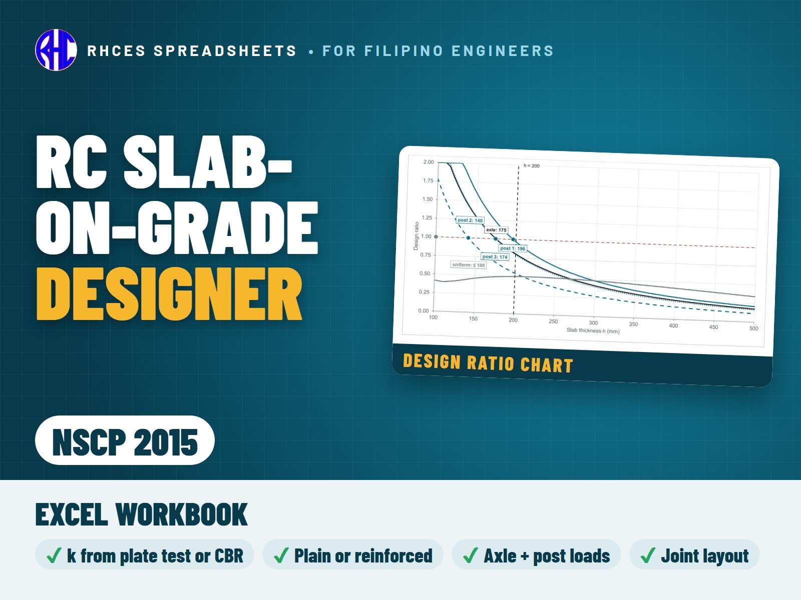
Preview of RC Slab-on-Grade Designer (NSCP 2015)
Structural

RC Slab-on-Grade Designer (NSCP 2015)

Design one concrete slab on ground (slab-on-grade) of uniform thickness for a warehouse, industrial, commercial or residential floor, on a subgrade with an optional granular sub-base. NSCP 2015 401.4.7 exempts floor slabs on ground that carry no loads from the structure, so the thickness comes from the published methods with service loads and safety factors, while NSCP 2015 supplies the concrete, durability, cover, spacing, laps, punching and bearing rules. Subgrade k from a plate load test, CBR or soil type, with the composite k on top of the sub-base. Plain slabs with sawcut joints, or one or two layers of distributed steel; dowelled, aggregate-interlock or free-edge joints.

Loads: one forklift or vehicle axle (from the rated capacity, service weight and axle share, or typed; single or dual wheels; solid or pneumatic tyres; load repetitions for the fatigue safety factor), up to 4 rows of rack posts or point loads (back-to-back racks as a 2 × 2 post group, single racks or single posts, at a joint or not) and one uniform storage load with a fixed or variable aisle layout.

Wheels and posts by PCA (default), Westergaard and Meyerhof, all three side by side, the chosen one driving the statuses; flexural strength from the code modulus of rupture 0.62√f'c by default, or a tested value. Checks: flexure in the interior and at joints for each load and the thickness each case needs; the uniform-load aisle moment (Hetenyi) and soil pressure; punching shear around base plates and tyres by the code equations (Table 414.5.5.1, or 422.6.5.2 for two layers) with combined perimeters for close loads; bearing; joint spacing, sawcut depth and dowels; distributed steel by subgrade drag and the 0.1 % minimum, cover, spacing and laps. A switch for a slab that carries loads from the structure or acts as a tie adds the code plain-concrete checks under factored loads.

Live drawings show the slab section at a joint, the axle and post-group plans with punching perimeters, the design ratio against slab thickness and the joint layout; the 33-line summary reports demand, capacity, ratio and PASS / FAIL / CHECK, with the required thickness and one overall result. Not covered: fibre-reinforced, post-tensioned, jointless and pile-supported slabs, slabs carrying columns or walls, line and wall loads, multi-axle trucks, mixed-traffic fatigue, curling analysis, dowel capacity, expansive soils and settlement. The Read Me lists the items taken from a single published source that are worth confirming.

Every result is a visible Excel formula, with printed NSCP 2015 clause and page references for the code items. Includes the Excel workbook. A worked A4 sample calculation can be previewed with View sample on the store page. One licence per engineer or office.

Excel · A4 calc sheets + live slab section, axle & post plans, ratio chart & joint layout
₱449.00View sample
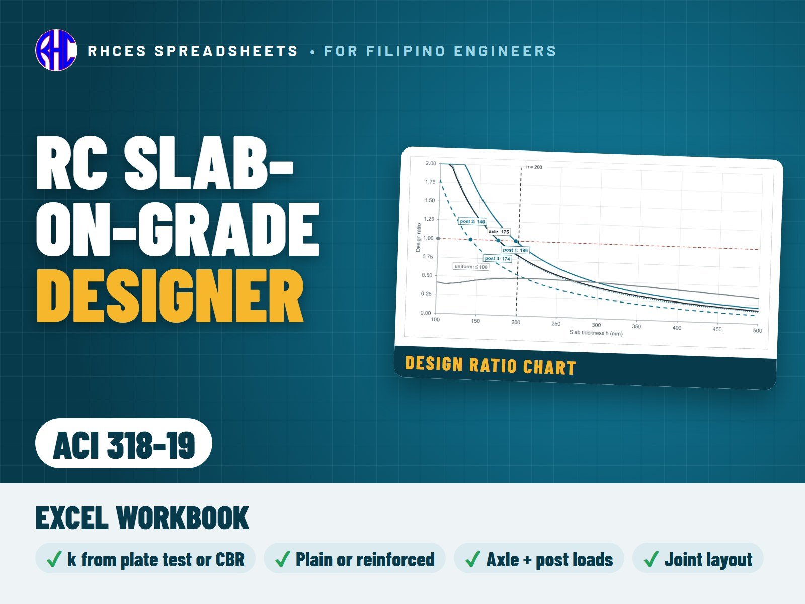
Preview of RC Slab-on-Grade Designer (ACI 318-19)
Structural

RC Slab-on-Grade Designer (ACI 318-19)

Design one concrete slab on ground (slab-on-grade) of uniform thickness for a warehouse, industrial, commercial or residential floor, on a subgrade with an optional granular sub-base (SI units). ACI 318-19 1.4.8 exempts floor slabs on ground that carry no loads from the structure (R1.4.8 points to ACI 360R), so the thickness comes from the published methods with service loads and safety factors, while ACI 318-19 supplies the concrete, durability, cover, spacing, laps, punching and bearing rules. Subgrade k from a plate load test, CBR or soil type, with the composite k on top of the sub-base. Plain slabs with sawcut joints, or one or two layers of distributed steel; dowelled, aggregate-interlock or free-edge joints.

Loads: one forklift or vehicle axle (from the rated capacity, service weight and axle share, or typed; single or dual wheels; solid or pneumatic tyres; load repetitions for the fatigue safety factor), up to 4 rows of rack posts or point loads (back-to-back racks as a 2 × 2 post group, single racks or single posts, at a joint or not) and one uniform storage load with a fixed or variable aisle layout.

Wheels and posts by PCA (default), Westergaard and Meyerhof, all three side by side, the chosen one driving the statuses; flexural strength from the code modulus of rupture 0.62√f'c by default, or a tested value. Checks: flexure in the interior and at joints for each load and the thickness each case needs; the uniform-load aisle moment (Hetenyi) and soil pressure; punching shear around base plates and tyres by the code equations (Table 14.5.5.1, or 22.6.5.2 with the size factor for two layers) with combined perimeters for close loads; bearing; joint spacing, sawcut depth and dowels; distributed steel by subgrade drag and the 0.1 % minimum, cover, spacing and laps. A switch for a slab that carries loads from the structure or acts as a tie adds the code plain-concrete checks under factored loads.

Live drawings show the slab section at a joint, the axle and post-group plans with punching perimeters, the design ratio against slab thickness and the joint layout; the 33-line summary reports demand, capacity, ratio and PASS / FAIL / CHECK, with the required thickness and one overall result. Not covered: fibre-reinforced, post-tensioned, jointless and pile-supported slabs, slabs carrying columns or walls, line and wall loads, multi-axle trucks, mixed-traffic fatigue, curling analysis, dowel capacity, expansive soils and settlement. The Read Me lists the items taken from a single published source that are worth confirming.

Every result is a visible Excel formula, with ACI 318-19 section references for the code items. Includes the Excel workbook. A worked A4 sample calculation can be previewed with View sample on the store page. One licence per engineer or office. Looking for the Philippine code? See the NSCP 2015 edition.

Excel · A4 calc sheets + live slab section, axle & post plans, ratio chart & joint layout · SI units
₱449.00View sample
Preview of RC Shear Wall Designer (NSCP 2015)
Structural

RC Shear Wall Designer (NSCP 2015)

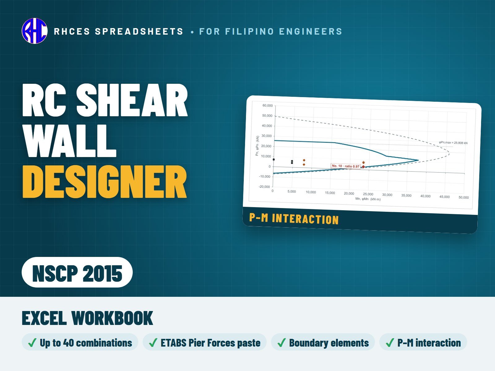
Design one section of a cast-in-place reinforced-concrete structural (shear) wall at a time, usually the critical section at the base, to NSCP 2015 Section 411 and, for special structural walls, 418.10: rectangular, with web bars in one or two curtains and optional boundary zones at both ends. Type the factored Pu, Mu and Vu of up to 40 combinations or paste the ETABS Pier Forces table (ETABS 22 or older layouts). The top displacement for the boundary-element check is typed from your analysis.

P-M interaction by strain compatibility for every combination (φ by Table 421.2.2). Checks: in-plane shear and its limit (418.10.4, or 411.5.4 for ordinary walls) with the φ = 0.60 rule of 421.2.4.1; the need for special boundary elements, displacement- or stress-based (418.10.6.2, 418.10.6.3), and their extent, width, Ash, hoop spacing and hx (418.10.6.4) and height, or the boundary ties of 418.10.6.5; minimum web steel, curtains, spacing and the 50 mm clear spacing of 425.2.1; shear friction across the joint (422.9); development and Class B laps. Special-wall shear is the Vu of your analysis, not amplified (418.10.3).

Live drawings show the plan section, the boundary element, the elevation and the P-M diagram with every combination; the 42-line summary reports demand, capacity, ratio and PASS / FAIL, with one overall result. Rectangular, symmetrically reinforced walls only, with the same boundary zone (or none) at both ends: flanged, C, L and barbell walls, openings, coupling beams, wall piers (screened only) and out-of-plane design are not covered.

Every result is a visible Excel formula with printed NSCP 2015 clause and page references. Includes the Excel workbook. A worked A4 sample calculation can be previewed with View sample on the store page. One licence per engineer or office.

Excel · A4 calc sheets + live plan section, boundary element, elevation & P-M diagram
₱449.00View sample
Preview of RC Shear Wall Designer (ACI 318-19)
Structural

RC Shear Wall Designer (ACI 318-19)

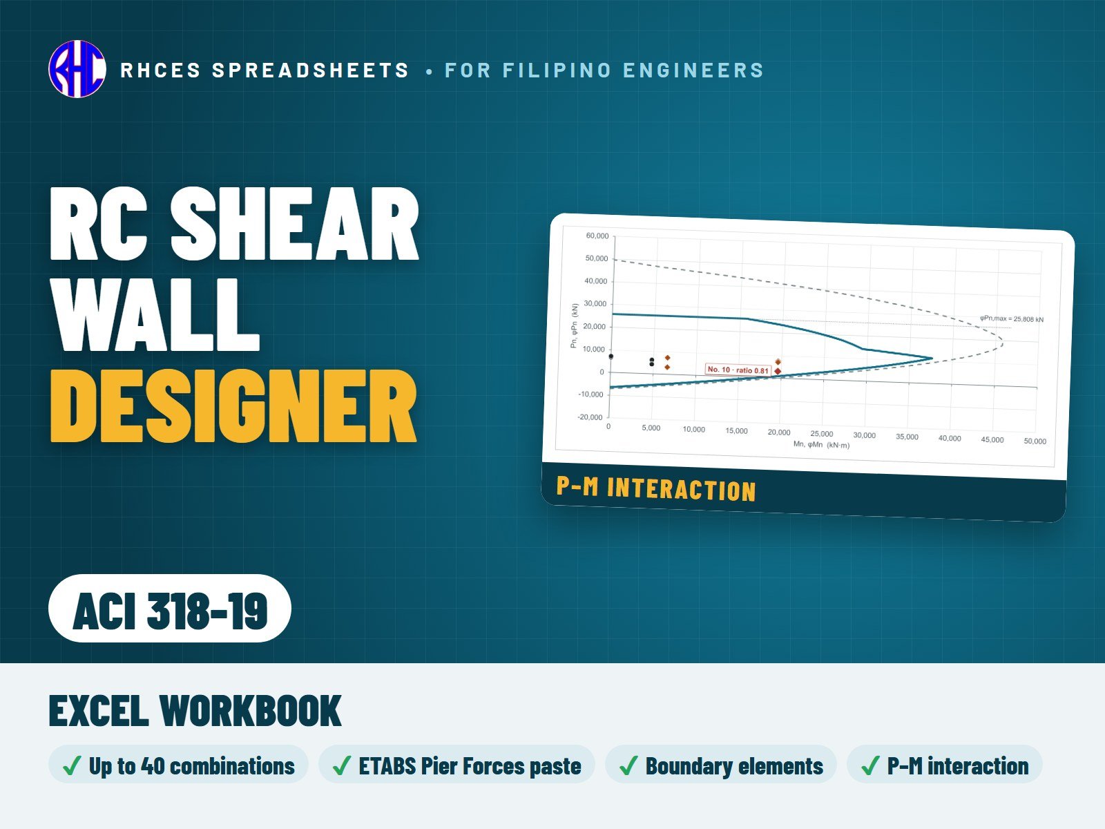
Design one section of a cast-in-place reinforced-concrete structural (shear) wall at a time, usually the critical section at the base, to ACI 318-19 Chapter 11 and, for special structural walls, 18.10, with the seismic basis of ASCE 7-22 (SI units): rectangular, with web bars in one or two curtains and optional boundary zones at both ends. Type the factored Pu, Mu and Vu of up to 40 combinations or paste the ETABS Pier Forces table (ETABS 22 or older layouts). The top displacement for the boundary-element check is typed from your analysis.

P-M interaction by strain compatibility for every combination, with the probable moment Mpr. Checks: in-plane shear (special walls: Ve = Ωv ωv Vu not above 3 Vu, 18.10.3.1, with one Ωv for the wall per note [1] of Table 18.10.3.1.2) and its limit; the need for special boundary elements, displacement-based with the drift capacity check (18.10.6.2) or stress-based (18.10.6.3), and their extent, width, Ash, spacing, hx, hoop legs, web crossties and floor concrete (18.10.6.4) and height, or the boundary ties of 18.10.6.5; minimum web steel, end reinforcement (18.10.2.4), curtains and spacing; shear friction and joint roughening; development and Class B laps, the no-lap zone above the critical section (18.10.2.3(c)) and a flag for the Ktr rule of 25.4.2.2 and 25.5.1.5 on Grade 550 and 690 bars spaced closer than 150 mm.

Live drawings show the plan section, the boundary element, the elevation and the P-M diagram with every combination; the 48-line summary reports demand, capacity, ratio and PASS / FAIL, with one overall result. Rectangular, symmetrically reinforced walls only, with the same boundary zone (or none) at both ends: flanged, C, L and barbell walls, openings, coupling beams, wall piers (screened only) and out-of-plane design are not covered. The ASCE 7-22 items follow published secondary sources; the Read Me lists them and what is still to be confirmed.

Every result is a visible Excel formula with ACI 318-19 section references. Includes the Excel workbook. A worked A4 sample calculation can be previewed with View sample on the store page. One licence per engineer or office. Looking for the Philippine code? See the NSCP 2015 edition.

Excel · A4 calc sheets + live plan section, boundary element, elevation & P-M diagram · SI units
₱449.00View sample
Preview of RC Cistern Designer (NSCP 2015)
Structural

RC Cistern Designer (NSCP 2015)

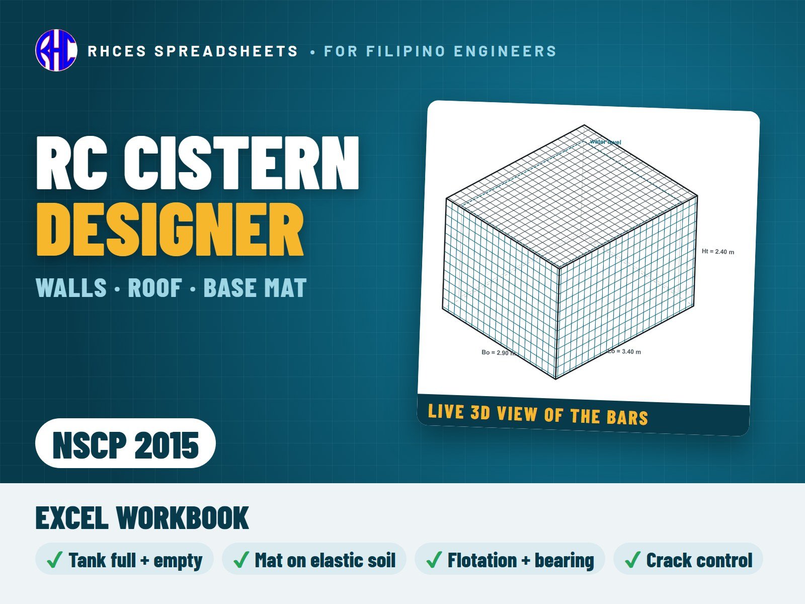
Design a whole rectangular reinforced-concrete cistern (water tank) by NSCP 2015: the four walls, the roof slab and the base slab, for a buried, partly buried or on-grade tank, with a roof slab or an open top. Type the inside length, width and height, the water depth, the thicknesses, the backfill, groundwater and surcharge, the roof loads, the allowable bearing and the bars (diameter and spacing) of every layer.

Every member is checked for the tank full without backfill (the water test) and the tank empty with backfill, surcharge and groundwater; the base also for the tank full with backfill. The walls are plates fixed at the corners, hinged at the roof or free at an open top, and take the worse of a fixed and a hinged base. The base slab is designed as a mat foundation on elastic soil (or a rigid mat), with the wall-base joint, soil contact and peak bearing. Each face gets flexure with direct tension, shear, minimum steel, bar spacing, cover and crack control by the service steel stress (0.2 or 0.1 mm crack class), plus flotation and bearing. A design check summary gives one result: CISTERN ADEQUATE, REVISE CISTERN or CHECK INPUTS. Live drawings follow the inputs: a section and a plan with the bars, a 3D view of the bars at their real spacing, a reinforcement schedule and 10 force-diagram charts.

Every result is a visible Excel formula with printed NSCP 2015 clause references, and BS 8007 references for liquid-tightness (NSCP 2015 has no chapter for liquid-retaining structures). Includes the Excel workbook and a 25-page user manual (A4 PDF) that takes the worked example step by step, with hand checks. A worked A4 sample calculation can be previewed with View sample on the store page. One licence per engineer or office.

Excel · A4 calc sheets + live section, plan, 3D view & force diagrams · 2 files incl. user manual
Includes 2 files: Excel workbook: RC Cistern Designer, NSCP 2015 · User manual, A4 (25 pages)
₱699.00View sample
Preview of RC Retaining Wall Designer (NSCP 2015)
Structural

RC Retaining Wall Designer (NSCP 2015)

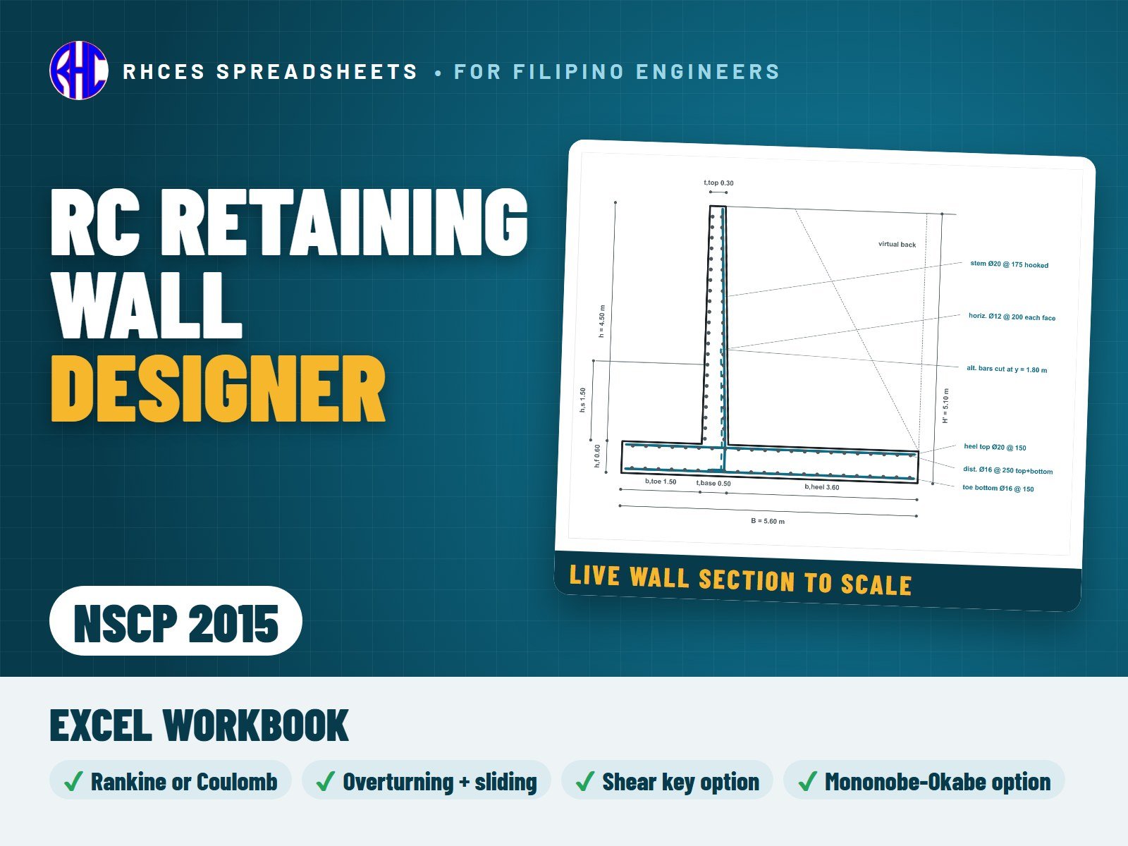
Design a cantilever reinforced-concrete retaining wall per metre run to NSCP 2015: battered stem, level or sloping backfill, surcharge, soil over the toe and an optional reinforced shear key. Earth pressure by Rankine or Coulomb, not below the minimum soil lateral load of Table 209-1 for the backfill class, or per your soil report.

Stability on allowable stress design loads (206.6): overturning and sliding (friction, adhesion, passive and key) with a factor of safety of at least 1.5, the resultant in the middle third, bearing pressure and Meyerhof bearing capacity, plus an optional Mononobe-Okabe seismic check on D + H + E/1.4 for both signs of kv. The stem, heel, toe and key are designed for the NSCP combinations with 1.6H and Ev = 0.5 Ca I D: flexure, one-way shear (Eq. 422.5.5.1, no size effect), minimum steel, the horizontal stem steel of Table 411.6.1, crack control, the 50 mm clear spacing of 425.2.1, cover, development and hooks, shear friction at the stem-footing joint and the cut-off of alternate stem bars. Grade 275 and 415 bars can be entered.

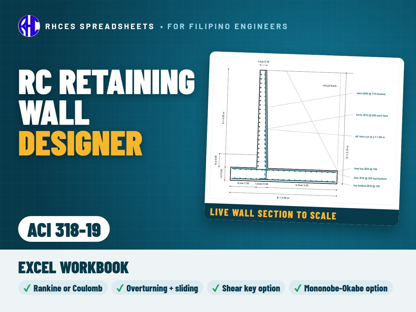
A to-scale wall section redraws itself as you type, and the 52-line summary reports demand, capacity, ratio and PASS / FAIL for every check, with one overall result. Basement (at-rest) walls, water pressure, settlement and global stability are not covered.

Every result is a visible Excel formula with printed NSCP 2015 clause and page references. Includes the Excel workbook. A worked A4 sample calculation can be previewed with View sample on the store page. One licence per engineer or office.

Excel · A4 calc sheets + live to-scale wall section
₱449.00View sample
Preview of RC Retaining Wall Designer (ACI 318-19)
Structural

RC Retaining Wall Designer (ACI 318-19)

Design a cantilever reinforced-concrete retaining wall per metre run to ACI 318-19 (SI units): battered stem, level or sloping backfill, surcharge, soil over the toe and an optional reinforced shear key. Earth pressure by Rankine or Coulomb, with a minimum fluid pressure for a level backfill that you set.

Stability under service loads with your factors of safety: overturning, sliding (friction, adhesion, passive and key), the resultant in the middle third, bearing pressure and Meyerhof bearing capacity, plus an optional Mononobe-Okabe seismic check for both signs of kv. The stem, heel, toe and key are designed for Table 5.3.1 with 1.6H: flexure (tension-controlled), one-way shear by Table 22.5.5.1 with the size effect (which 13.2.6.2 lets you neglect in the footing), minimum steel 0.0018 Ag, crack control, clear spacing, cover, development and hooks, the 25.4.2.2 rule for fy 550 MPa bars, shear friction at the stem-footing joint and the cut-off of alternate stem bars.

A to-scale wall section redraws itself as you type, and the 53-line summary reports demand, capacity, ratio and PASS / FAIL for every check, with one overall result. Basement (at-rest) walls, water pressure, settlement and global stability are not covered.

Every result is a visible Excel formula with ACI 318-19 section references. Includes the Excel workbook. A worked A4 sample calculation can be previewed with View sample on the store page. One licence per engineer or office. Looking for the Philippine code? See the NSCP 2015 edition.

Excel · A4 calc sheets + live to-scale wall section · SI units
₱449.00View sample
Preview of RC Diaphragm Designer (NSCP 2015)
Structural

RC Diaphragm Designer (NSCP 2015)

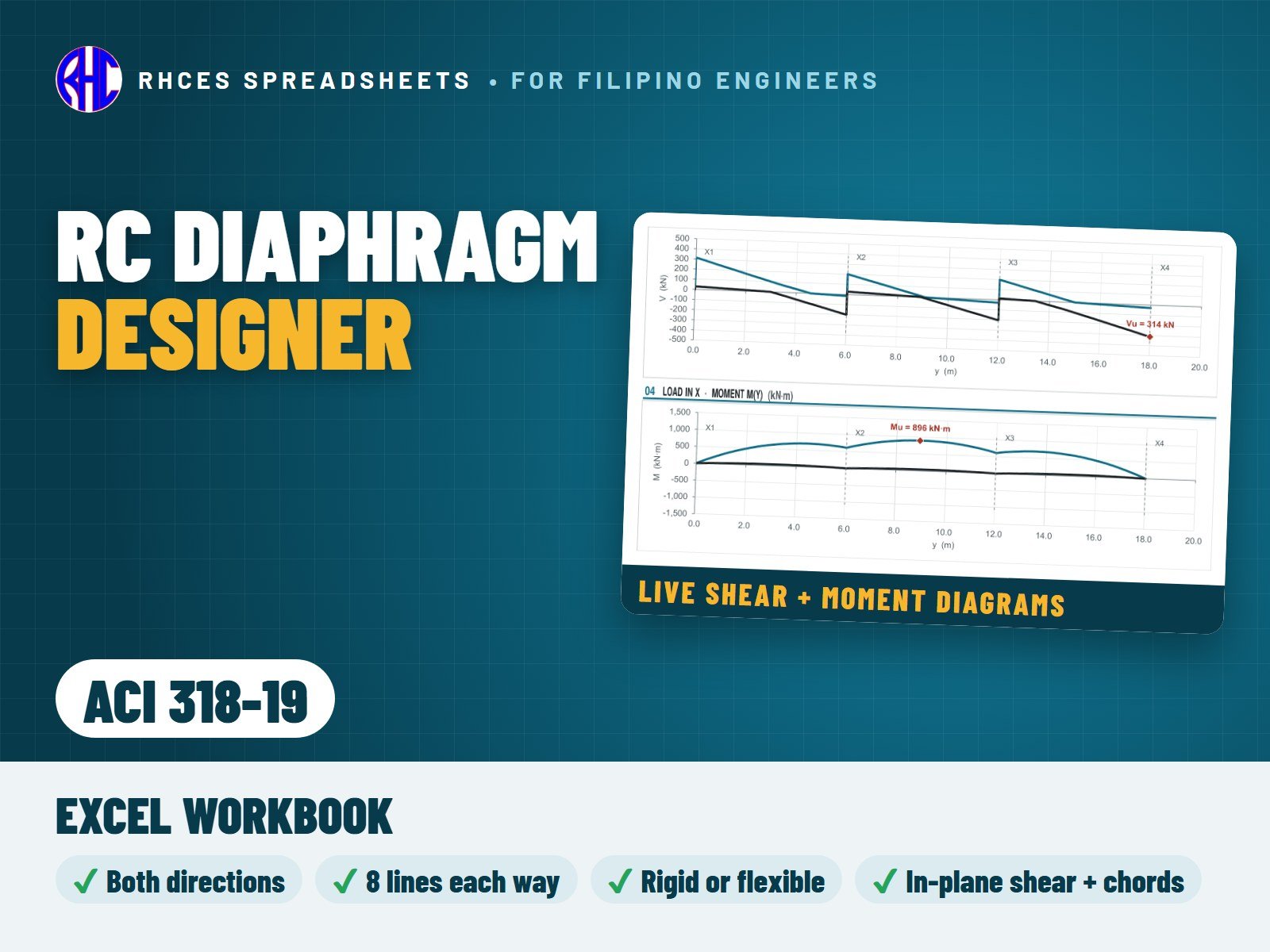
Design a cast-in-place reinforced-concrete floor or roof diaphragm (solid slab of uniform thickness) in both plan directions by the beam analogy of NSCP 2015 Section 412 and the seismic rules of 418.12: a rectangular plan with up to 8 lines of walls or frames each way and one opening, with storey forces for up to 50 levels worked out from the base shear and period, or typed.

Fpx by Eq. 208-22 within 0.5 to 1.0 Ca I wpx (or the simplified procedure, or typed), plus wind and transfer forces; line reactions by a flexible, rigid (with torsion) or envelope model, with live shear and moment diagrams. Checks: in-plane shear and its limit, chords, collectors for the Eq. 208-22 force and Em = Ωo Eh (tension, compression, the stress limit and hoops of 418.12.7.5, splice zones), shear friction to the walls and collectors, collector extension, development and Class B laps, minimum thickness, minimum slab steel and bar spacing (50 mm clear, 425.2.1), and the net section, chords, trimmers and drag bars at the opening.

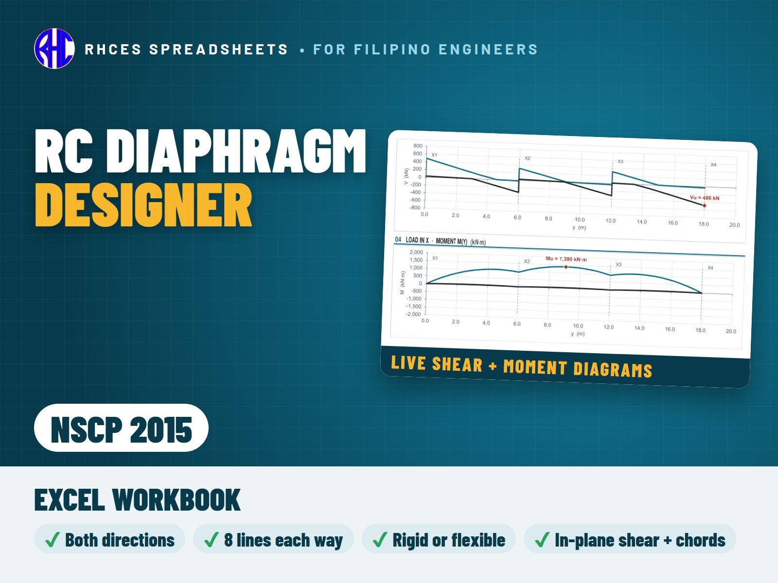
A live plan shows the lines, collectors, chords and opening; the 65-line summary reports demand, capacity, ratio and PASS / FAIL for every check, with one overall result. Precast, prestressed and non-rectangular diaphragms, the gravity (out-of-plane) design of the slab and the combined axial force and gravity moment of beam collectors are not covered.

Every result is a visible Excel formula with printed NSCP 2015 clause and page references. Includes the Excel workbook. A worked A4 sample calculation can be previewed with View sample on the store page. One licence per engineer or office.

Excel · A4 calc sheets + live plan, shear & moment diagrams · both directions
₱449.00View sample
Preview of RC Diaphragm Designer (ACI 318-19)
Structural

RC Diaphragm Designer (ACI 318-19)

Design a cast-in-place reinforced-concrete floor or roof diaphragm (solid slab of uniform thickness) in both plan directions by the beam analogy of ACI 318-19 Chapter 12 and the seismic rules of 18.12, with the diaphragm forces of ASCE 7-22 12.10 (SI units): a rectangular plan with up to 8 lines of walls or frames each way and one opening, with storey forces for up to 50 levels worked out from the base shear and period, or typed.

Fpx by Eq. 12.10-1 within the limits of 12.10-2 and 12.10-3 (or typed), plus wind and transfer forces; line reactions by a flexible, rigid (with torsion) or envelope model, with live shear and moment diagrams. Checks: in-plane shear and its limit, chords, collectors by the force sets of 12.10.2.1 with Ωo and the Exception 1 cap (tension, compression, the average tensile stress of 18.12.7.5, the stress limit and hoops of 18.12.7.6, splice zones), shear friction with roughened joints in SDC D to F, collector extension, development and Class B laps (with 25.4.2.2), minimum thickness, minimum slab steel and bar spacing, and the net section, chords, trimmers and drag bars at the opening.

A live plan shows the lines, collectors, chords and opening; the 66-line summary reports demand, capacity, ratio and PASS / FAIL for every check, with one overall result. Precast, prestressed and non-rectangular diaphragms, the gravity (out-of-plane) design of the slab and the combined axial force and gravity moment of beam collectors are not covered. The ASCE 7-22 items follow published secondary sources; the Read Me lists them and what is still to be confirmed.

Every result is a visible Excel formula with ACI 318-19 section references. Includes the Excel workbook. A worked A4 sample calculation can be previewed with View sample on the store page. One licence per engineer or office. Looking for the Philippine code? See the NSCP 2015 edition.

Excel · A4 calc sheets + live plan, shear & moment diagrams · both directions · SI units
₱449.00View sample
1Click Buy now
2Pay by GCash, Maya or QR Ph on PayMongo’s secure page, or with PayPal
3Your Download button appears as soon as payment clears